


263
10.10 Notes on Using the UART and Example for Using the UART
10.10 Notes on Using the UART and Example for Using the UART
This section provides an example for use of the UART and notes on using the UART.
■
Notes on Using the UART
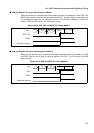
Set the communication mode while UART operation is stopped. Data transmitted during mode
setting cannot be assured.
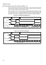
If the timing for writing to the serial output data register (SODR) matches the timing for
requesting a receiver interrupt (RDRF = 1) during UART operation in synchronous transfer
mode (mode 2), the communication control circuit may stop. To prevent this problem, write to
the SODR after data transfer or immediately after transmission begins.
■
Example for Use of the UART
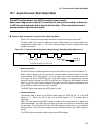
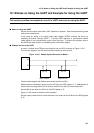
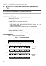
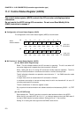
In mode 1, multiple slave CPUs are connected to one host CPU as shown in Figure 10.10-1.
This resource supports only the communication interface on the host end.
Figure 10.10-1 Sample System Structure for Mode 1
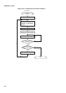
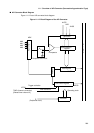
Communication begins with address data transfer by the host CPU.
Address data is indicated by the fact that the A/D bit of the SCR register is "1". Address data is
used to select the target slave CPU so that the host CPU can start to communicate with it.
Normal data is sent when the A/D bit of the SCR register is "0".
Figure 10.10-2 shows a flowchart for this operation.
Since the parity check function cannot be used in this mode, set the PEN bit of the SCR register
to "0".
SO
SO SI SO SI
Host CPU
Slave CPU#0 Slave CPU#1
SI