143
4.16 Relationship between Data Bus Widths and Control Signals
❍
8-bit bus width
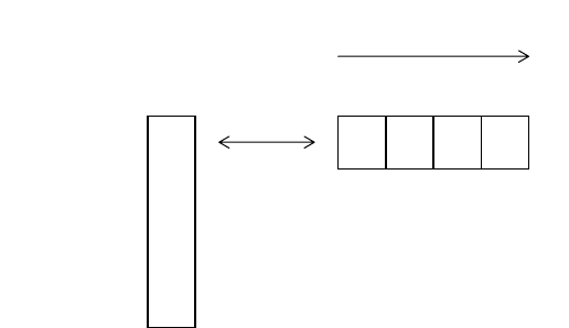
Figure 4.16-7 Relationship between Internal Register and External Data Bus for 8-bit Bus Width
■
External Bus Access
Figure 4.16-8 and Figure 4.16-9 show external bus access (in a 16-bit or 8-bit bus width) in
words, half-words, and bytes. These figures also show the following items:
• Access byte location
• Program address and output address
• Bus access count
<Note>
Because the MB91F109 detects no misalignment, even if the lower 2 bits of the address
specified by the program for word access are "00", "01", "10", or "11", the lower 2 bits of the
output address are set to "00". When these bits are "00" or "01" in half-word access, they are
set to "00", and when the bits are "10" or "11", they are set to "10".
"00" "01" "10" "11"
Read/Write
AA AA BB CC DD
BB
CC
DD
D31
D23
D15
D07
D31
Internal register External bus
Lower part of the output address


