


248
CHAPTER 10 UART
10.2 Serial Mode Register (SMR)
The serial mode register (SMR) specifies the UART operation mode.
Set the operation mode while UART operation is stopped. Do not write to the register
during UART operation.
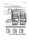
■
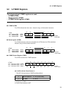
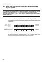
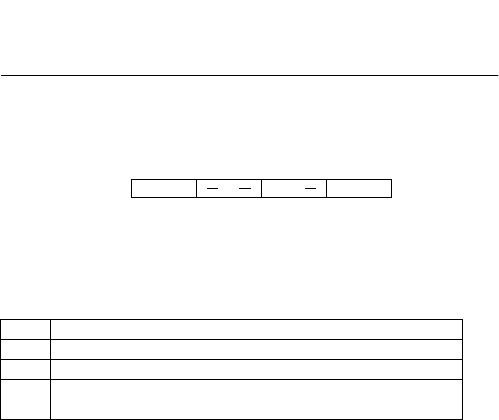
Configuration of Serial Mode Register (SMR)
The configuration of the serial mode register (SMR) is shown below:
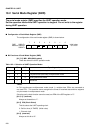
■
Bit Functions of Serial Mode Register (SMR)
[bit 7, 6] MD1, MD0 (MoDe select)
These bits select the UART operation mode.
<Note>
In CLK asynchronous multiprocessor mode (mode 1), multiple slave CPUs are connected to
one host CPU. This resource cannot recognize the format of received data and thus supports
only the master in multiprocessor mode.
Since the parity check function cannot be used, set PEN of the SCR register to "0".
[bit 5, 4] (reserved)
Always set these bits to "1".
[bit 3] CS0 (Clock Select)
This bit selects the UART operating clock.
0: Built-in timer (U-TIMER) (Initial value)
1: External clock
[bit 2] (reserved)
Always set this bit to "0".
76543210
SMR 00001F
H
Address: 000023
H
MD1 MD0 CS0 SCKE SOE 00--0-00
B
000027
H
R/W R/W W R/W R/W
Initial value
Table 10.2-1 Selection of UART Operation Modes
Mode MD1 MD0 Operating mode
0 0 0 Asynchronous (start-stop) normal mode (Initial value)
1 0 1 Asynchronous (start-stop) multiprocessor mode
2 1 0 CLK synchronous mode
– 1 1 Reserved