


202
CHAPTER 5 I/O PORTS
5.1 Outline of I/O Ports
When a resource is not allowed to use the corresponding pin as an I/O, the MB91F109
allows the pin to be used as an I/O port.
■
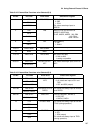
Basic Block Diagram of I/O Ports
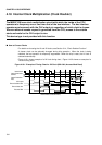
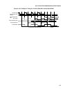
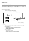
Figure 5.1-1 shows the basic I/O port configuration.
Figure 5.1-1 Basic I/O Port Block Diagram
■
I/O Port Registers
I/O ports are composed of a port data register (PDR) and a data direction register (DDR).
❍
Input mode (DDR="0")
• PDR read: Reads the output level of the corresponding external pin.
• PDR write: Writes a value to the PDR.
❍
Output mode (DDR = "1")
• PDR read: Reads the PDR value.
• PDR write: Outputs the PDR value to the corresponding pin.
Data Bus
0
1
PDR read
0 pin
1
DDR
PDR
Resource input
Resource output
Resource output permission
PDR: Port Data Register
DDR: Data Direction Register