


381
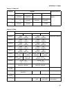
APPENDIX B Interrupt Vectors
Reserved for the system 47 2F ICR31 340
H
000FFF40
H
Reserved for the system 48 30 - 33C
H
000FFF3C
H
Reserved for the system 49 31 - 338
H
000FFF38
H
Reserved for the system 50 32 - 334
H
000FFF34
H
Reserved for the system 51 33 - 330
H
000FFF30
H
Reserved for the system 52 34 - 32C
H
000FFF2C
H
Reserved for the system 53 35 - 328
H
000FFF28
H
Reserved for the system 54 36 - 324
H
000FFF24
H
Reserved for the system 55 37 - 320
H
000FFF20
H
Reserved for the system 56 38 - 31C
H
000FFF1C
H
Reserved for the system 57 39 - 318
H
000FFF18
H
Reserved for the system 58 3A - 314
H
000FFF14
H
Reserved for the system 59 3B - 310
H
000FFF10
H
Reserved for the system 60 3C - 30C
H
000FFF0C
H
Reserved for the system 61 3D - 308
H
000FFF08
H
Reserved for the system 62 3E - 304
H
000FFF04
H
Delay interrupt cause bit 63 3F ICR47 300
H
000FFF00
H
System reservation (used by
REALOS) *
3
64 40 – 2FC
H
000FFEFC
H
System reservation (used by
REALOS) *
3
65 41 – 2F8
H
000FFEF8
H
Used for INT instruction 66
to
255
42
to
FF
–2F4
H
to
000
H
000FFEF4
H
to
000FFC00
H
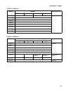
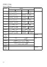
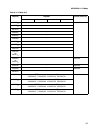
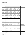
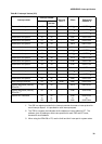
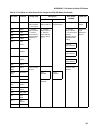
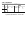
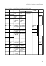
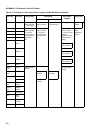
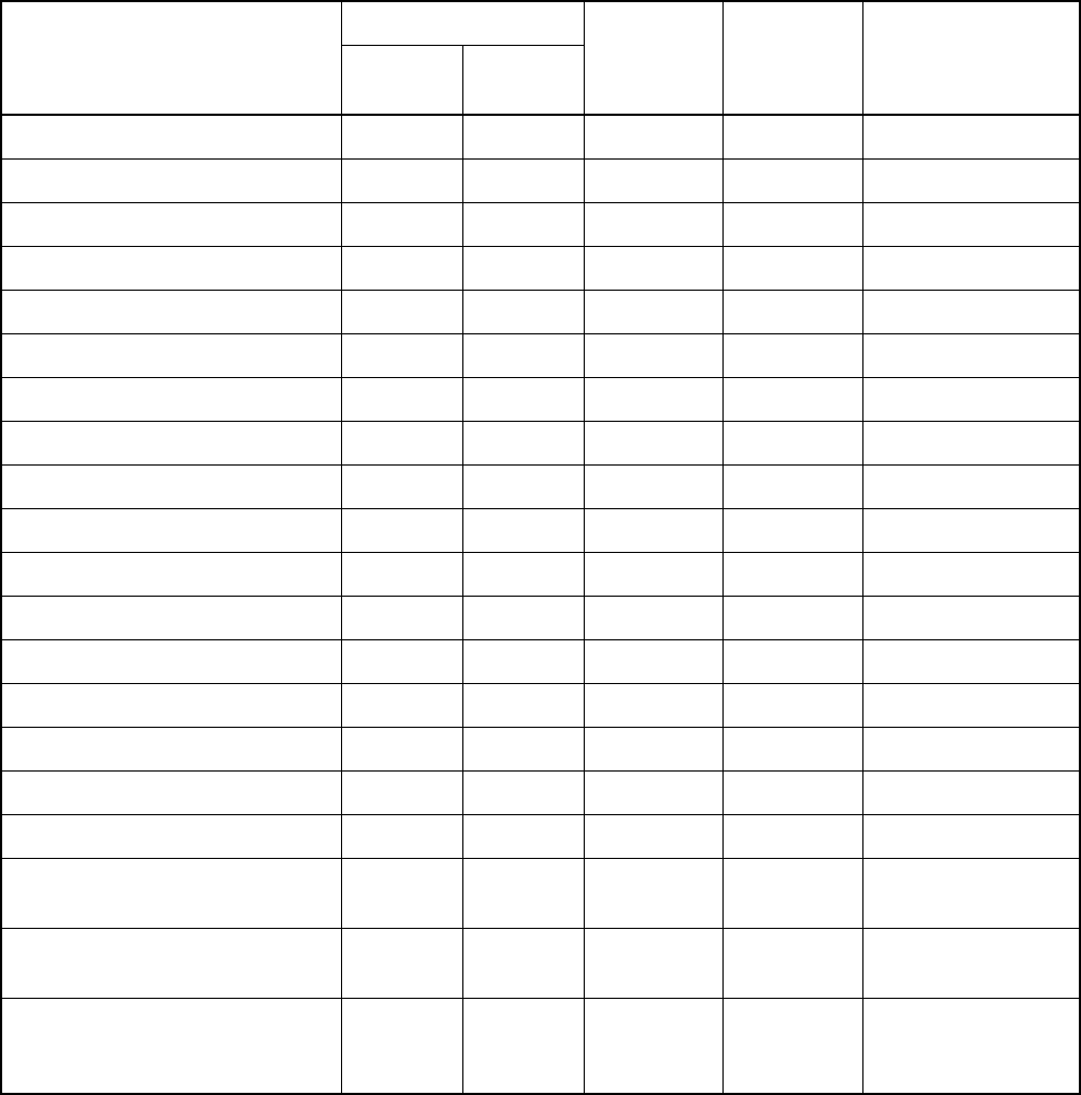
Table B-2 Interrupt Vectors (2/2)
Interrupt cause
Interrupt number
Interrupt
level *1
Offset
TBR default
address *2
Decimal Hexa-
decimal
*1 The ICR is a register provided in the interrupt controller that sets an interrupt level for
each interrupt request. It is provided for each interrupt request.
*2 The TBR is a register that indicates the first address of vector tables for EIT. The
address, given by adding an offset value specified for each TBR and EIT factor,
becomes a vector address.
*3 When using the REALOS or FR, use the 0x40 and 0x41 interrupts for system codes.