


108
CHAPTER 3 CLOCK GENERATOR AND CONTROLLER
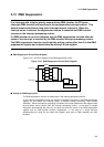
3.15 Example of PLL Clock Setting
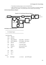
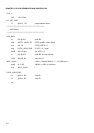
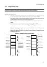
This section provides an example of PLL clock setting and an example of the
assembler source.
■
Example of PLL Clock Setting
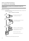
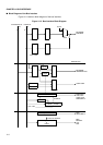
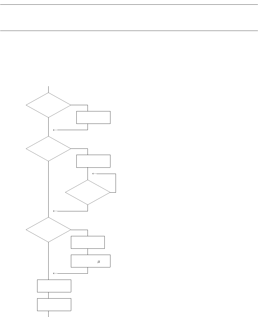
An example of the procedure for switching to 25 MHz operation using PLL (in the case of 12.5
MHz oscillation) is shown below:
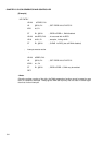
Figure 3.15-1 Example of PLL Clock Setting
<Notes>
• The DBLON, VSTP, and SLCT0 bits can be set in any order.
No
CHC = 1
CHC
<
-1
Ye s
No
DBLON= 0
DBLON
<
-0
Ye s
DBLACK = 0
No
Ye s
No
VSTP = 0
VSTP
<
-0
Ye s
WAIT 100
SLCT0
<
-1
CHC
<
-0
When making a PLL setting, switch the clock
to the divide-by-two clock in advance.
Since this model does not support the clock doubler
function, use the initial setting as is.
Restart the PLL if it is stopped. Design software
so that 100 microseconds or more are allowed until
oscillation stabilizes after the PLL restarts.
Switch the PLL output tap to 25 MHz.
Switch the divide-by-two clock to the PLL clock.
S