


370
APPENDIX A I/O Maps
APPENDIX A I/O Maps
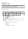
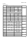
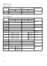
The addresses listed from Table A.1 to Table A.6 are assigned to the registers of the
functions for peripherals that are built-in in the MB91F109.
■
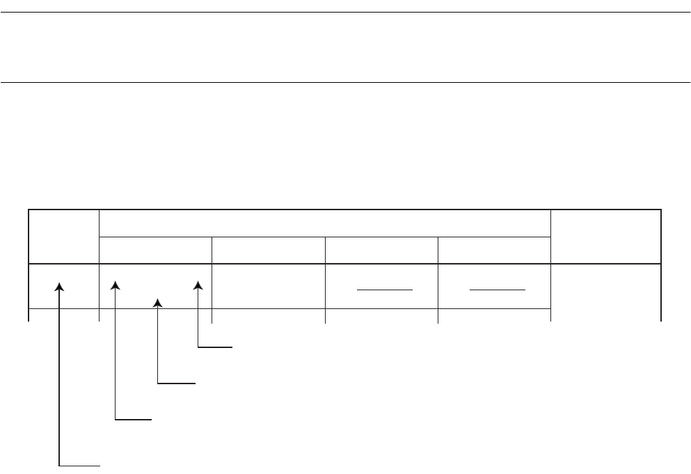
How to Read the I/O Maps
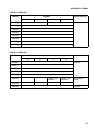
<Note>
The register bit value has one of the following initial values:
"1": Initial value "1"
"0": Initial value "0"
"X": Initial value "X"
"– ": No register actually exists at this position.
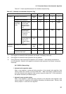
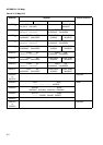
Address
Register
Internal resource
Port data register
+0 +1 +2 +3
000000
H PDR3 [R/W]
XXXXXXXX
PDR2 [R/W]
XXXXXXXX
Read/write attribute
Initial register value after reset
Register name (the register listed in the first column is at address 4n, the register listed in
the second column is at address 4n+1, ...)
Leftmost register address (the first column register is on the MSB side of data in word access mode)