


109
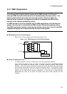
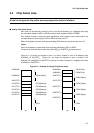
3.15 Example of PLL Clock Setting
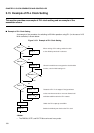
• The peripheral operating frequency must not exceed 25 MHz.
• Design software so that 100 microseconds or more are allowed until oscillation stabilizes
after the PLL VC0 restarts. Do not allow cache on/off to cause a wait time shortage.
■
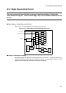
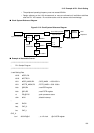
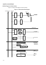
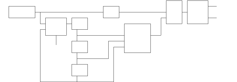
Clock System Reference Diagram
Figure 3.15-2 Clock System Reference Diagram
■
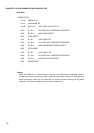
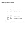
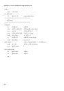
Example of Assembler Source
; ************************************************************
; PLL Sample Program
; ************************************************************
; Load Setting Data
ldi:20 #GCR, R0
ldi:20 #PCTR,R1
ldi:8 #GCR_MASK,R2 ; GCR_MASK = 0000 0001 b
ldi:8 #PCTR_MASK,R3 ; PCTR_MASK = 0000 1000 b
ldub @R0,R4 ; read GCR register
ldub @R1,R5 ; read PCTR register
st PS,@-R15 ; push processor status
stilm #0x0 ; disable interrupt
;
and R4,R2
beq CHC_0
bra CHC_1
CHC_0:
borl #0001B,@r0 ; to 1/2 clock @r0=GCR register
CHC DBLON CPU
12.5MHz 1/2 1 DBLACK
0
Input of oscillation
1/2
50MHz SLCT1,0
--
01
VSTP
1/2 00
STAND-BY
25MHz
1/2
12.5MHz
Input of divide-by-two clock
Input of PLL clock
PCTR register
GCR register
Peripheral
PLL