


268
CHAPTER 11 A/D CONVERTER (Successive approximation type)
11.1 Overview of A/D Converter (Successive Approximation
Type)
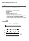
The A/D converter converts analog input voltage to digital values.
■
Characteristics of A/D Converter
• Minimum conversion time: 5.6
µ
s/ch (for 25 MHz system clock)
• Built-in sample & hold circuit
• 10- bit resolution
• Program selection of analog input from four channels
• Single conversion mode: One channel is selected and converted.
• Scan conversion mode: Multiple consecutive channels are converted. Up to four
channels can be programmed.
• Continuous conversion mode: The specified channel is converted repeatedly.
• Convert-and-stop mode: When one channel is converted, the converter stops and waits
for the next activation (the beginning of conversion can be synchronized).
• DMA transfer activated by an interrupt
• Choices of software, external trigger (falling edge), and reload timer (rising edge) for
activation
■
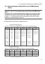
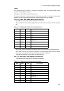
A/D Converter Registers
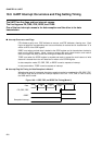
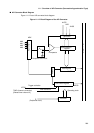
Figure 11.1-1 shows the A/D converter registers.
Figure 11.1-1 A/D Converter Registers
15 0
ADCS
ADCR
16bit
bit 15 14 13 12 11 10 9 8
BUSY INT INTE PAUS STS1 STS0 STRT
(ADCS)
bit 76543210
MD1 MD0 ANS2 ANS1 ANS0 ANE2 ANE1 ANE0
bit 15 14 13 12 11 10 9 8
(ADCR)
bit 76543210
76543210
98
Control status register
Data register