


243
9.3 U-TIMER Operation
9.3 U-TIMER Operation
This section explains how to calculate the U-TIMER baud rate and also explains the
cascade mode.
■
Calculating the Baud Rate
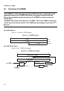
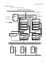
The UART uses the underflow flip-flop (f.f. in the figure) of the corresponding U-TIMER (U-
TIMERx --> UARTx, x = 0, 1, 2) as the baud rate clock source.
❍
Asynchronous (start-stop) mode
The UART uses the U-TIMER output by dividing it by 16.
❍
CLK synchronous mode
■
Cascade Mode
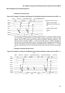
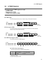
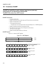
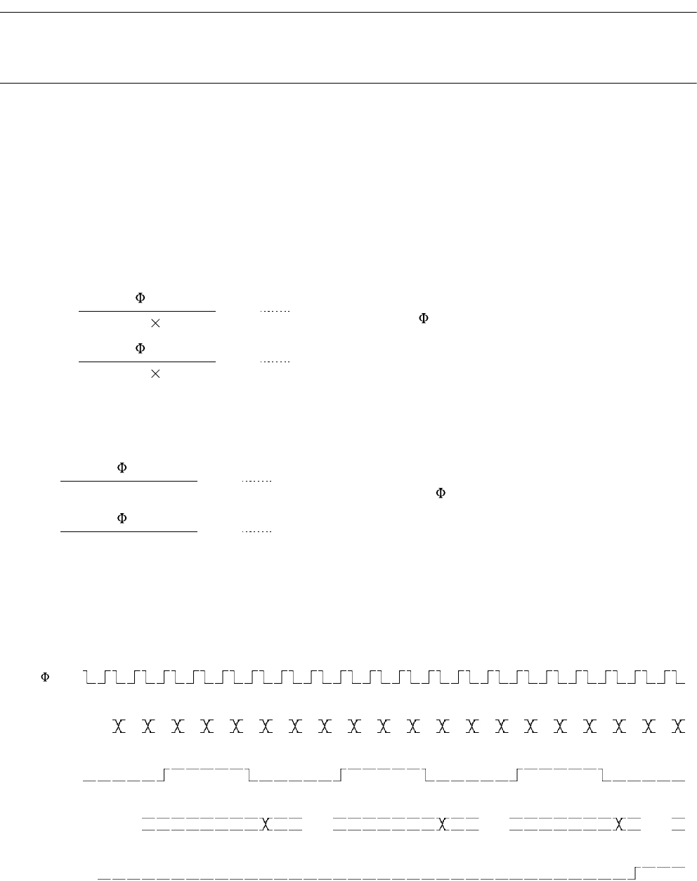
U-TIMER channels 0 and 1 can be used in cascade mode. Figure 9.3-1 shows an example of
cascade mode in which UTIMR channel 0 is set to 0100 and UTIMR channel 1 is set to 0002.
Figure 9.3-1 Example of Using U-TIMER Channels 0 and 1 in Cascade Mode
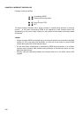
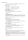
n: UTIMR (Reload value)
bps = UCC1=0
(2n+2)
16
: Peripheral machine clock frequency
(variable with the gear)
bps = UCC1=1
(2n+3) 16
n: UTIMR (Reload value)
bps = UCC1=0
(2n+2)
bps = UCC1=1
(2n+3)
: Peripheral machine clock frequency
(variable with the gear)
UTIM ch.1 01 00 02 01 00 02 01 00 02 01 00 02 01 00 02 01 00 02 01 00
f.f. ch.1
UTIM ch.0 0002 0001 0000 0100
f.f. ch.0