


69
2.10 Operation Mode
2.10 Operation Mode
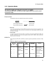
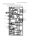
Two operation modes, bus mode and access mode, are available.
The mode pins (MD2, MD1, and MD0) and mode register (MODR) are used to control
the operation mode.
■
Operation Mode
Two operation modes, bus mode and access mode, are available.
❍
Bus mode
In bus mode, the operations of internal ROM and external access functions are controlled. The
mode pins (MD2, MD1, MD0), and the M1 and M0 bits of the mode register (MODR) are used
for control in this mode.
❍
Access mode
In access mode, external data bus width is controlled. The mode pins (MD2, MD1, MD0), and
the BW1 and BW0 bits of the area mode registers (AMD0, AMD1, AMD32, AMD4, AMD5) are
used for control in this mode.
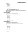
■
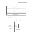
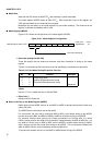
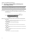
Mode Pins
Three mode pins, MD2, MD1, and MD0, are used for operation specification as shown in Table
2.10.1.
@@@@@@@@
Bus mode
Access mode
Single chip
Internal-ROM-external bus
External-ROM-external bus
16-bit bus width
8-bit bus width
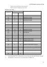
Table 2.10-1 Mode Pins and Setting Modes
Mode pins Mode name Reset
vector
access area
External data
bus width
Remarks
MD
2
MD1 MD
0
0 0 0 External
vector mode 0
External 8 bit External-ROM-
external bus mode
0 0 1 External
vector mode 1
External 16 bit External-ROM-
external bus mode
010 - - - Reserved
0 1 1 Internal vector
mode
Internal (Mode register) Single chip mode
1-- - - - Reserved