


300
CHAPTER 14 PWM TIMER
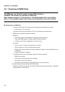
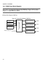
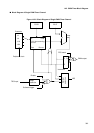
14.1 Overview of PWM Timer
The PWM timer can efficiently output accurate PWM waveforms.
The MB91F109 contains four channels of PWM timer.
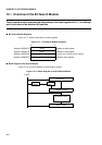
Each channel consists of a 16-bit counter, a 16-bit data register with a cycle setting
buffer, a 16-bit compare register with a duty cycle setting buffer, and a pin controller.
■
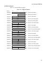
Characteristics of PWM Timer
• The count clock for the 16-bit counter can be selected from the following four types:
• Internal clock:
φ
,
φ
/4,
φ
/16,
φ
/64
• The counter value can be initialized to "FFFF
H
" by resetting or a counter borrow.
• PWM output is enabled through each channel.
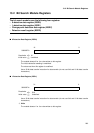
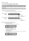
•Registers
• Cycle setting register: Data register for reloading containing a buffer
• Duty cycle setting register: Compare register containing a buffer
• Transfer from the buffer is triggered by a counter borrow.
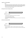
•Pin control
• The pin is set to "1" when duty cycles match. (Priority)
• The pin is reset to "0" when a counter borrow occurs.
• Because the constant output level mode is supported, output can be maintained at a low
or high level.
• Polarity specification is enabled.
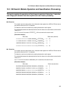
• The following events can be selected as causes for interrupt requests:
• PWM timer activation
• Occurrence of counter borrow (cycle matching)
• Occurrence of duty cycle matching
• Occurrence of counter borrow (cycle matching) or duty cycle matching
An interrupt request thus caused can start DMA transfer.
• Software or another interval timer can activate multiple channels simultaneously. Restarting
during operation is also enabled.