


305
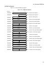
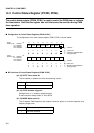
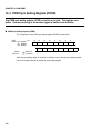
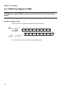
14.3 Control Status Register (PCNH, PCNL)
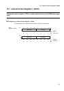
[bit 12] RTRG: Restart enable bit
This bit enables or disables restart by a software trigger or trigger input.
[bits 11, 10] CKS1, CKS0: Counter clock select bit
These bits select the counter clock for the 16-bit decrementing counter.
φ:
Peripheral machine clock
[bit 9] PGMS: PWM output mask selection bit
Setting this bit to "1" can mask the PWM timer so that it outputs only "0" or "1" regardless of
the mode, cycle, or duty cycle settings.
To maintain output at a high level in normal polarity mode or at a low level in inverse polarity
mode, write the same value to the cycle setting and duty cycle setting registers, thereby
inverting the output of the above mask values.
[bit 8]: Reserved
[bits 7, 6] EGS1, SGS0: Trigger input edge select bits
These bits select the edge applicable to the start source selected by general control register
1.
In any edge mode, setting the software trigger bit to "1" enables the software trigger.
0 Disable restart (Initial value)
1 Enable restart
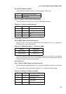
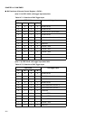
Table 14.3-1 Selection of the Count Clock
CKS1 CKS0 Cycle
00
φ
(Initial value)
01
φ/4
10
φ/16
11
φ/64
Table 14.3-2 PWM Output When "1" is Written to PGMS
Polarity PWM output
Normal polarity Output of L
Inverse polarity Output of H
Table 14.3-3 Selection of Trigger Input Edge
EGS1 EGS0 Edge selection
0 0 Invalid (initial value)
0 1 Rising edge
1 0 Falling edge
1 1 Both edges