


353
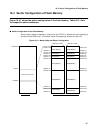
16.1 Outline of Flash Memory
■
Execution Status of the Automatic Algorithm
When the automatic algorithm is started in CPU programming mode, its operation status can be
checked with the internal Busy or Ready signal (RDY/BUSYX). The level of this signal can be
read from the "RDY" bit of the flash memory status register.
When the "RDY" bit is "0", the automatic algorithm performs a write or read and another Read
or Erase command cannot be accepted. Data cannot be read from a flash memory address
either.
Data read when the "RDY" bit is "0" determines the setting of a hardware sequence flag
indicating flash memory status (see Section 16.6, "Starting the Automatic Algorithm").
■
Interrupt Control
When the automatic algorithm sequence ends, an interrupt request can be issued to the CPU,
thereby making it possible to quickly recognize the end of an automatic algorithm sequence that
has continued for an extended period.
The "RDYINT" and "INTE" bits of the flash memory status register control the interrupt at the
end of the automatic algorithm.
The "RDYINT" bit is an interrupt flag set at the end of the automatic algorithm. When the rising
edge of the internal Ready or Busy signal (RDY/BUSYX) from "0" to "1" is detected, the interrupt
flag is set to "1". When the "INTE" bit is "1" and the "RDYINT" bit is set, an interrupt request is
output to the CPU.
When canceling the interrupt request, set the "RDYINT" or "INTE" bit to "0".
■
Writing by ROM Writer
This flash memory enables writing by a device-external ROM writer.
During writing by a device-external ROM writer, the pin functions equivalent to the functions of
the single flash memory MBM29LV200 are assigned to the external pins of the device and the
FR-CPU stops operation. In CPU mode, address line connections are changed and the
mapping in the memory area changes. For details, refer to the specification of the
corresponding ROM writer.