


270
CHAPTER 11 A/D CONVERTER (Successive approximation type)
11.2 Control Status Register (ADCS)
The control status register (ADCS) controls the A/D converter and displays status
information.
Do not rewrite the ADCS during A/D conversion. Do not use a Read Modify Write
(RMW) instruction to access it.
■
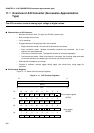
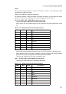
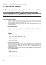
Configuration of Control Status Register (ADCS)
The configuration of the control status register (ADCS) is shown below:
■
Bit Function of Control Status Register (ADCS)
[bit 15] BUSY (BUSY flag and stop)
Read: This bit indicates whether the A/D converter is operating. The bit is set when A/D
conversion begins and is cleared when the conversion is finished.
Write: Setting this bit to "0" during A/D conversion forcibly stops the operation. The bit is
used for forced termination in continuous conversion or convert-and-stop mode.
The bit indicating information on operation cannot be set to "1". An RMW instruction reads
"1" from the bit.
In single mode, the bit is cleared when A/D conversion is finished.
In continuous conversion or convert-and-stop mode, the bit is not cleared until it is set to "0"
to forcibly terminate A/D conversion.
The bit is initialized to "0" when the register is reset.
Do not perform forced termination and software activation simultaneously (BUSY = 0, STRT
= 1).
[bit 14] INT (INTerrupt)
Data indication bit. This bit is set when conversion data has been written to the ADCR.
When the bit is set while INTE (bit 13) is "1", an interrupt request occurs and DMA starts if
the start of DMA transfer has been selected. Setting the bit to "1" has no effect.
Setting "0" or issuing the clear signal from the DMAC clears the bit.
bit 15 14 13 12 11 10 9 8
ADCS
Address:00003A
H
BUSY INT INTE PAUS STS1 STS0 STRT
00000000
R/W R/W R/W R/W R/W R/W W R/W
bit 76543210
MD1 MD0 ANS2 ANS1 ANS0 ANE2 ANE1 ANE0
00000000
R/W R/W R/W R/W R/W R/W R/W R/W
Initial value
Initial value
Bit attribute
Bit attribute