


289
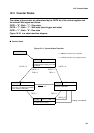
12.5 Counter States
12.5 Counter States
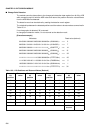
The states of the counter are determined by the CNTE bit of the control register and
the internal Wait signal as follows:
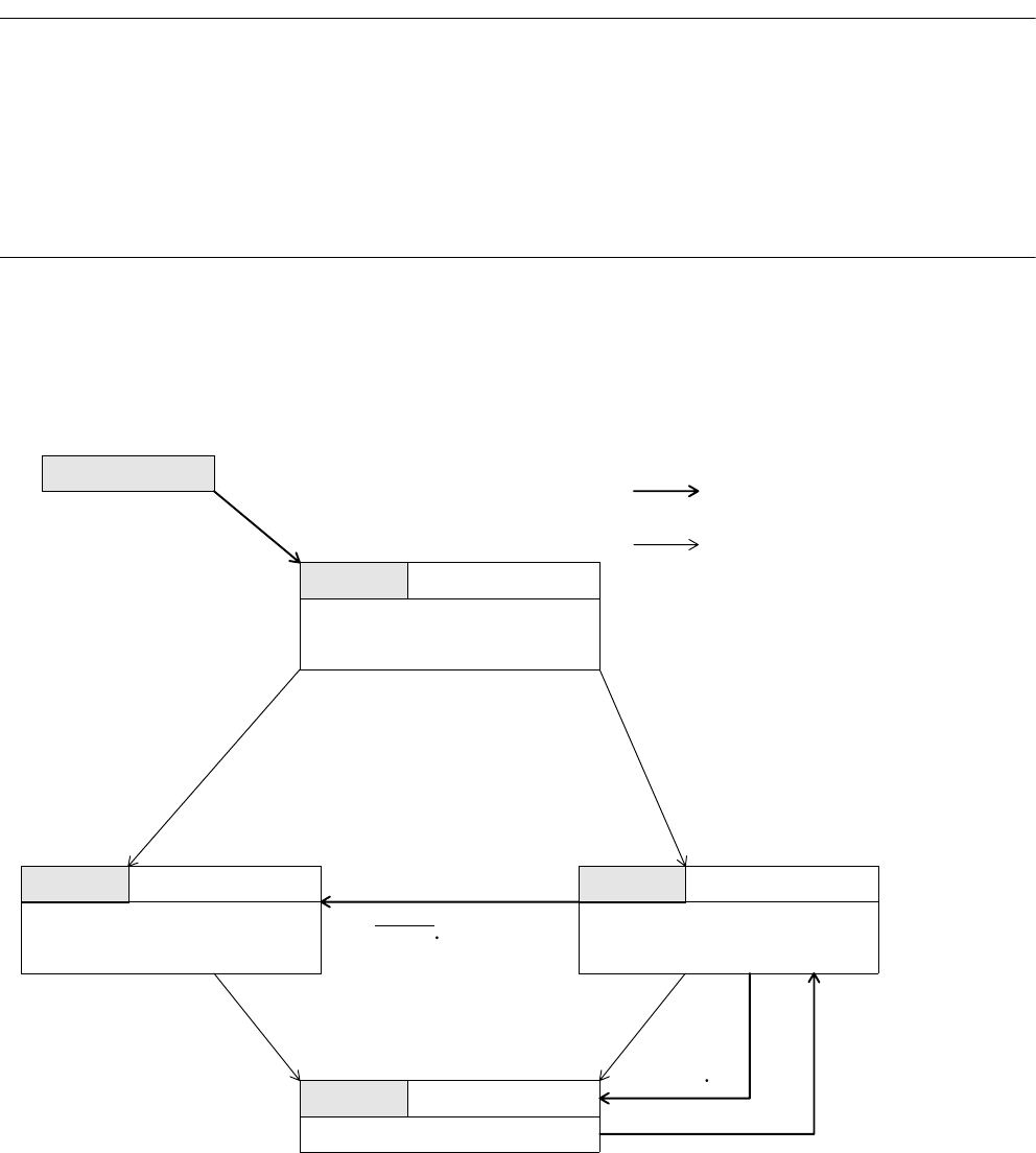
CNTE = "0", Wait = "1": Stop state
CNTE = "1", Wait = "1": Wait state (start trigger wait state)
CNTE = "1", Wait = "0": Run state
Figure 12.5-1 is a state transition diagram.
■
Counter States
Figure 12.5-1 Counter States Transition
CNTE=0,WAIT=1
CNTE='0'
'
CNTE='0'
CNTE='1' CNTE='1'
TRG='0' TRG='1'
CNTE=1,WAIT=1 CNTE=1,WAIT=0
RELD
TRG='1' TRG='1'
RELD UF
CNTE=1,WAIT=0
STOP
RESET
WAIT
UF
LOAD
RUN
State transition by hardware
State transition by register access
Counter: Operates
The contents of the reload register
are loaded to the counter.
Loading is completed.
Counter: Holds the value at a stop.
Immediately after resetting, this value
is undefined.
Counter: Holds the value at a stop.
The value is undefined immediately
after resetting until loading.