


258
CHAPTER 10 UART
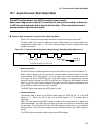
10.8 CLK Synchronous Mode
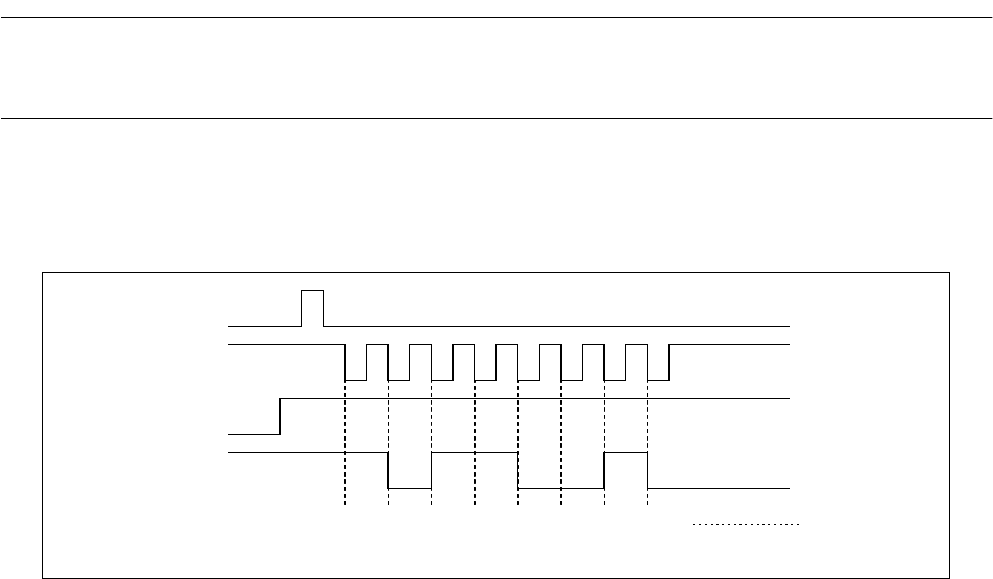
The UART handles only data of NRZ (nonreturn-to-zero) format. Figure 10.8-1 shows
the relationship between the transmission/reception clock and the data.
■
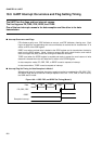
Format of Data Transferred in CLK Synchronous Mode
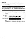
Figure 10.8-1 Format of Data Transferred in CLK Synchronous Mode (Mode 2)
When CS0 is set to "0" to select U-TIMER output, transmitting data automatically generates
synchronizing clock pulses for receiving data.
When the external clock is selected, clock pulses of exactly one byte must be supplied after
ensuring that there is data in the transmission data buffer SODR register of the UART on the
transmitting end (The TDRE flag is "0"). The mark level before and after transmission must also
be ensured.
The data length can only be eight bits, and no parity bit can be added. Since no start and stop
bits are used, only overrun errors are detected.
❍
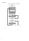
Initialization
The values that must be set in individual control registers for using CLK synchronous mode are
shown below:
• SMR register
• MD1, MD0: 10
• CS: Clock input
• SCKE: 1 for internal timer or 0 for external timer
• SOE: 1 for transmission or 0 for reception only
SC
RXE,TXE
SI,SO
LSB MSB
SODR write
Mark
(Mode 2)
1
1
1
1
0
00 0
The transferred data item is 01001101
B.