184
CHAPTER 4 BUS INTERFACE
❍
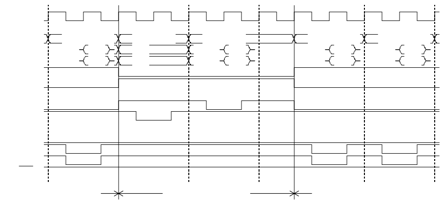
Combination of high-speed page mode and basic bus cycle
Figure 4.17-28 Example 4 of DRAM Interface Timing Chart in High-Speed Page Mode
[Explanation of operation]
• Even if the CS area switches and another CS area is accessed, RAS remains at "L" in high-
speed page mode.
Q4 Idle
CLK
A24-00 CS4X col.adr CS2X basic bus CS2X basic bus CS4X col.adr CS4X col.adr
D31-24
D23-16
CS2X
CS4X
RDX
WR0X
CS4:RAS
CS4:CASL
CS4:CASH
CS4:WE
CS4 high-speed page
CS2 basic bus
Q5 BA1 BA2 BA1 BA2 Q4 Q5 Q4 Q5
CS4 high-speed page
Write
Read Write
Read
Read
Read
Read
Read
Read
Read


