


99
3.11 Watchdog Function
3.11 Watchdog Function
The watchdog function detects program crashes.
If A5
H
and 5A
H
are not written to the watchdog reset postpone register within the
specified time due to a program crash, the watchdog timer issues a watchdog reset
request.
■
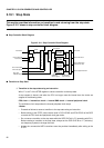
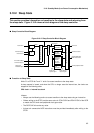
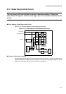
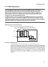
Watchdog Controller Block Diagram
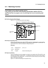
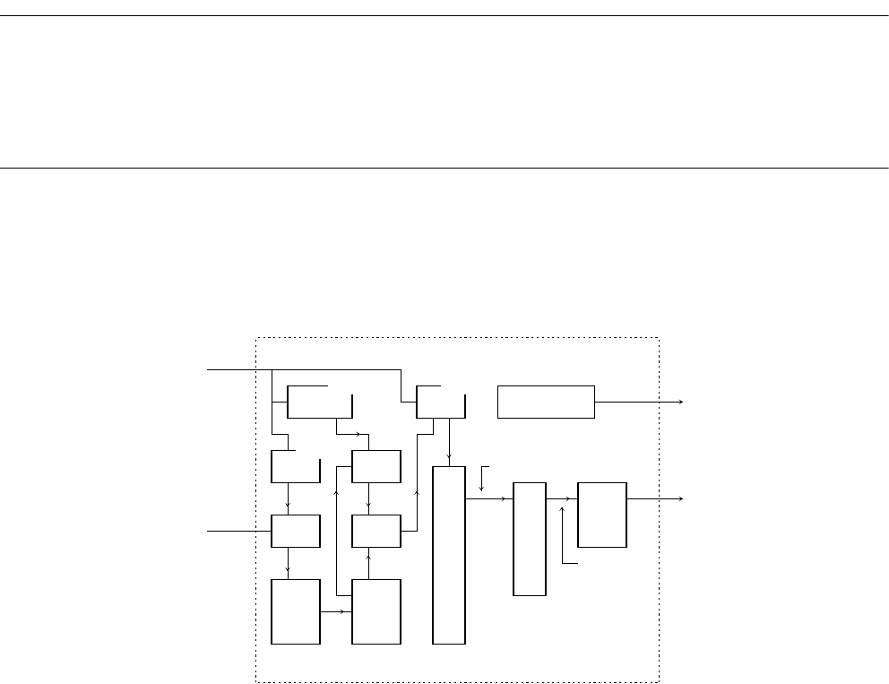
Figure 3.11.1 is a watchdog controller block diagram.
Figure 3.11-1 Watchdog Timer Block Diagram
■
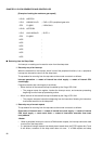
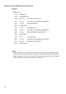
Starting the Watchdog Timer
Writing to the watchdog control register (WTCR) causes the watchdog timer to start operation.
For this operation, set the interval time of the watchdog timer using the WT1 and WT0 bits. The
interval time set first is valid but subsequent settings are ignored.
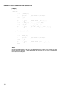
[Example]
■
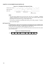
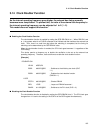
Postponing Resetting
Once the watchdog timer starts operation, a program must regularly write A5H and 5AH to the
watchdog reset postpone register (WPR). The watchdog reset flip-flop stores the falling edge of
the tap selected by the timebase timer. If the flip-flop has not been cleared at the second falling
edge, a reset signal is generated.
Figure 3.11.2 shows the watchdog timer operation timing.
WPR RSRR
A5&5A WDOG
clr
CTBR
WTx
and
Internal bus
Timebase timer
frequency division
output
Latch
Select
Edge
sense
circuit
Watch
dog
F/F
State transition control circuit
Timebase timer
Reset state transition
request signal
State decoder
Reset state
Reset
causing
F/F
Timebase timer
frequency division
output
Internal reset
LDI:8 #00000010b,R1 ; WT1,0=10
LDI:20 #WTCR,R2
STB R1,@R2 ; Starts the watchdog timer.