


172
CHAPTER 4 BUS INTERFACE
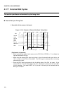
4.17.7 External Wait Cycles
This section provides an external wait cycle timing chart.
■
External Wait Cycle Timing Chart
❍
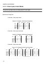
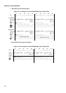
Bus width: 16 bits, access: half-words
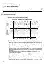
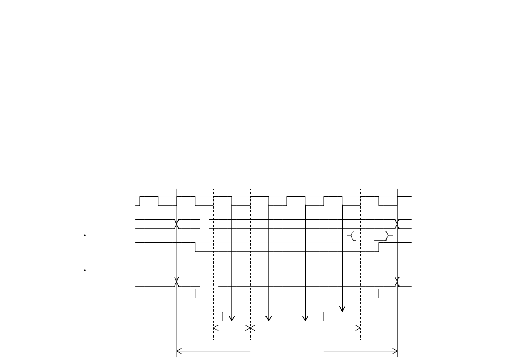
Figure 4.17-15 Example of External Wait Cycle Timing Chart
[Explanation of operation]
• When implementing external wait cycles, set the RDYE bit of EPCR0 to "1" to validate the
input of the external RDY pin.
• When using the external RDY signal, set at least 1 clock of automatic wait cycle; that is, set
"001" or more in the WTC bit of the AMD. The RDY signal is detected after, not during,
automatic wait cycles.
• Enter the RDY signal synchronously with the falling edge of the CLK pin output. If the
external RDY is "L" at the falling edge of the CLK, a wait cycle is entered and the same BA1
cycle is repeated. If the external RDY is "H", the end of the wait cycle is assumed and the
BA2 cycle is entered.
BA1 BA1 BA1 BA1 BA1 BA2
CLK
A24-00 #0
#0:1
D31-16
RDX
D31-16 #0,1
WR0X,1X
wait wait wait RDY
RDY
Automatic Wait by RDY
Bus cycle
Read
Write
wait