


321
14.13 Starting Multiple PWM Timer Channels
14.13 Starting Multiple PWM Timer Channels
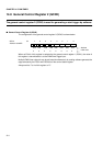
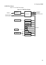
General control registers 1 and 2 (GCN1 and GCN2) can be used to start multiple PWM
timer channels.
Selecting a start trigger with the GCN1 register enables simultaneous start of multiple
channels.
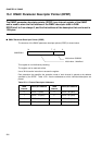
This section provides an example of starting multiple channels using software (based
on the GCN2 register) and another using the 16-bit reload timer.
■
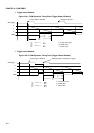
Starting Multiple PWM Timer Channels Via Software
Proceed as follows:
1. Set the cycle in PCSR.
2. Set the duty cycle in PDUT.
• Write to PCSR and then PDUT.
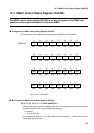
3. Set the source of trigger input for the channels to be started in GCN1.
• Leave the GCN1 in the initial state because GCN2 is used in this example.
(ch0 --> EN0, ch1 --> EN1, ch2 --> EN2, ch3 --> EN3)
4. Set the control status register for the channels to be started as follows:
• CNTE:1 --> Enable timer operation.
• STGR:0 --> Leave this bit as is because GCN2 is used to issue a start trigger.
• MDSE:0 --> PWM operation
• RTRG:0 --> Disable restart.
• CSK1, 0: 00 --> Count clock =
φ
• PGMS:0 --> Do not mask output.
(Bit 8 --> 0: Unused bit. Any value can be set.)
• EGS1, 0:01 --> Start at a rising edge.
• IREN:1 --> Enable interrupt requests.
• IRQF:0 --> Clear the interrupt cause.
• IRS1, 0:01 --> Issue an interrupt request when the counter generates a borrow.
• POEN:1 --> Enable PWM output.
• OSEL:0 --> Normal polarity
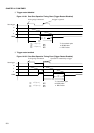
5. Write data to GCN2 to generate a start trigger.
• To start channels 0 and 1 simultaneously under the above settings, write "1" to EN0 and
EN1 of GCN2, which generates a rising edge and causes pulses to be output from PWM0
and PWM1.