


171
4.17 Bus Timing
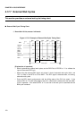
4.17.6 Automatic Wait Cycles
This section provides an automatic wait cycle timing chart.
■
Automatic Wait Cycle Timing Chart
❍
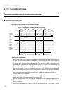
Bus width: 16 bits, access: half-word read/write
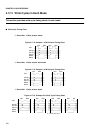
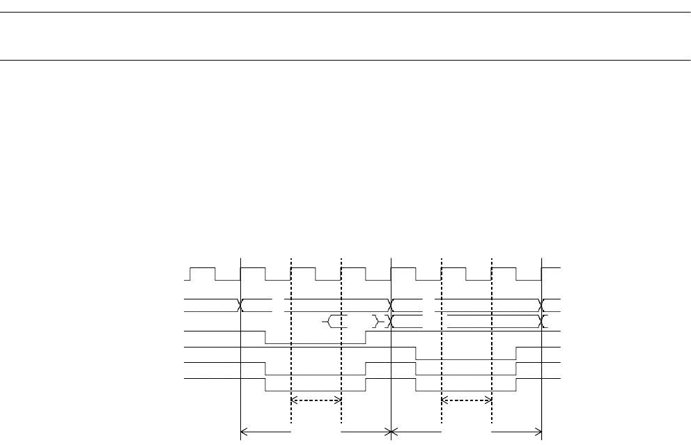
Figure 4.17-14 Example of Automatic Wait Cycle Timing Chart
[Explanation of operation]
• When implementing automatic wait cycles, set the WTC bit of the AMD register for each chip
select area.
• The above example is an example the WTC bits are set "001" to insert one wait bus cycle in
the usual bus cycles. In this case, it follows that "2 usual clock bus cycles" + "1 wait clock
cycle" = "3 clock bus cycles".
Up to 7 clock cycles of automatic wait (usual bus cycles: 9 clock cycles) can be specified.
BA1 BA1 BA2 BA1 BA1 BA2
CLK
A24-00 #0 #2
D31-16 #0:1 #2,3
RDX
WR0X,1X
(DACK0)
(EOP0)
Wait
Wait
Read
Write