


115
4.2 Chip Select Area
4.2 Chip Select Area
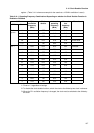
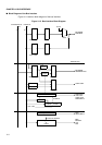
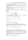
A total of six types of chip select area are prepared for the bus interface.
■
Setting Chip Select Areas
Each area can be optionally located in units of at least 64 kilobytes in a 4 gigabyte area using
the area select registers (ASR1 to ASR5) and area mask registers (AMR1 to AMR5).
If an attempt is made to access the area specified by these registers via the external bus, the
corresponding chip select signals CS0X to CS5X become active "L".
When the registers are reset, these pins excluding CS0X become inactive and are set to "H."
<Note>
Area 0 is allocated to a space other than the areas specified by ASR1 to ASR5.
At reset time, the external area other than 00010000
H
to 0005FFFF
H
becomes area 0.
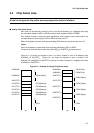
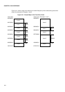
Figure 4.2.1 (a) shows an example of area 1 to area 5 located in units of 64 kilobytes from
00100000
H
to 0014FFFF
H
. Figure 4.2.1 (b) shows an example of area 1 located in 512
kilobytes from 00000000
H
to 0007FFFF
H
and area 2 to area 5 located in 1 megabyte units from
00100000
H
to 004FFFFF
H
.
Figure 4.2-1 Example of Setting Chip Select Areas
00000000
H
00000000
H
CS1X(512K)
00080000
H
CS0X(512K)
00080000
H
CS0X(1Mbyte) 000FFFFF
H
CS2X(1Mbyte)
000FFFFF
H
001FFFFF
H
0010FFFF
H
CS1X(64kbyte) CS3X(1Mbyte)
0011FFFF
H
CS2X(64kbyte) 002FFFFF
H
0012FFFF
H
CS3X(64kbyte) CS4X(1Mbyte)
0013FFFF
H
CS4X(64kbyte) 003FFFFF
H
0014FFFF
H
CS5X(64kbyte) CS5X(1Mbyte)
004FFFFF
H
CS0X CS0X
(a)
(b)