


56
CHAPTER 2 CPU
2.8.2 Interrupt Control Register (ICR)
The interrupt control register, which is provided in the interrupt controller, is used to
set the level for each interrupt request. The ICR is divided to correspond to individual
interrupt causes. The ICR is mapped in the I/O address space and accessed from the
CPU via the bus.
■
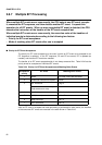
Configuration of Interrupt Control Register (ICR)
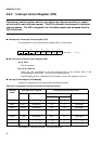
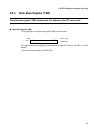
The configuration of the interrupt control register (ICR) is shown below:
■
Bit Functions of Interrupt Control Register (ICR)
[bit 4] ICR4
This bit is always 1.
[bit 3 to 0] ICR3 to 0
These four bits correspond to the four low-order bits of the interrupt level of the
corresponding interrupt cause. The bits can be read and written.
The bits together with bit 4 enable the ICR to specify a value in the range from 16 to 31.
■
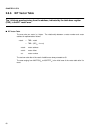
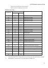
Interrupt Control Register (ICR) Mapping
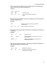
Table 2.8.2 Assignments of interrupt causes and interrupt vectors
See Chapter 8, "Interrupt Controller," for more information.
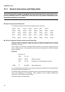
76543210
ICR4 ICR3 ICR2 ICR1 ICR0 ---11111
R R/W R/W R/W R/W
Initial value
Table 2.8-2 Assignments of Interrupt Causes and Interrupt Vectors
Interrupt
cause
Interrupt control register Corresponding interrupt vector
Number Address Number Address
Hexadecimal Decimal
IRQ00 ICR00 00000400
H
10
H
16 TBR+3BC
H
IRQ01 ICR01 00000401
H
11
H
17 TBR+3B8
H
IRQ02 ICR02 00000402
H
12
H
18 TBR+3B4
H
:
:
:
:
:
:
:
:
:
:
:
:
IRQ45 ICR45 0000042D
H
3D
H
61 TBR+308
H
IRQ46 ICR46 0000042E
H
3E
H
62 TBR+304
H
IRQ47 ICR47 0000042F
H
3F
H
63 TBR+300
H