


II CORE BLOCK: CPU AND OPERATING MODE
B-II-2-4 EPSON S1C33L03 FUNCTION PART
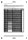
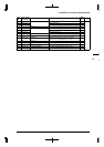
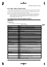
Trap Table
Table 2.1 shows the trap table in the C33 Core. Refer to the "S1C33000 Core CPU Manual" for details of
exceptions and Section II-5 in this manual, "ITC (Interrupt Controller)", for interrupts.
Serial interface Ch.2 and Ch.3 interrupts share the trap table for port input interrupts and 16-bit timer interrupts.
Refer to Section III-8, "Serial Interface", for details of the settings.
Table 2.1 Trap Table
HEX
No.
Vector number
(Hex address)
Exception/interrupt name Exception/interrupt factor
IDMA
Ch.
Priority
00(Base) Reset Low input to the reset pin – High
1–3 reserved – –
↑
44(Base+10) Zero division Division instruction –
55 reserved – –
66(Base+18) Address error exception Memory access instruction –
70x0 or 0x60000 Debugging exception brk instruction, etc. –
88(Base+1C) NMI Low input to the NMI pin –
9–11 reserved – –
C 12(Base+30) Software exception 0 int instruction –
D 13(Base+34) Software exception 1 int instruction –
E 14(Base+38) Software exception 2 int instruction –
F 15(Base+3C) Software exception 3 int instruction –
10 16(Base+40) Port input interrupt 0 Edge (rising or falling) or level (High or Low) 1
11 17(Base+44) Port input interrupt 1 Edge (rising or falling) or level (High or Low) 2
12 18(Base+48) Port input interrupt 2 Edge (rising or falling) or level (High or Low) 3
13 19(Base+4C) Port input interrupt 3 Edge (rising or falling) or level (High or Low) 4
14 20(Base+50) Key input interrupt 0 Rising or falling edge –
15 21(Base+54) Key input interrupt 1 Rising or falling edge –
16 22(Base+58) High-speed DMA Ch.0 High-speed DMA Ch.0, end of transfer 5
17 23(Base+5C) High-speed DMA Ch.1 High-speed DMA Ch.1, end of transfer 6
18 24(Base+60) High-speed DMA Ch.2 High-speed DMA Ch.2, end of transfer –
19 25(Base+64) High-speed DMA Ch.3 High-speed DMA Ch.3, end of transfer –
1A 26(Base+68) IDMA Intelligent DMA, end of transfer –
27–29 reserved – –
1E 30(Base+78) 16-bit programmable timer 0 Timer 0 comparison B 7
1F 31(Base+7C) Timer 0 comparison A 8
32–33 reserved – –
22 34(Base+88) 16-bit programmable timer 1 Timer 1 comparison B 9
23 35(Base+8C) Timer 1 comparison A 10
36–37 reserved – –
26 38(Base+98) 16-bit programmable timer 2 Timer 2 comparison B 11
27 39(Base+9C) Timer 2 comparison A 12
40–41 reserved – –
2A 42(Base+A8) 16-bit programmable timer 3 Timer 3 comparison B 13
2B 43(Base+AC) Timer 3 comparison A 14
44–45 reserved – –
2E 46(Base+B8) 16-bit programmable timer 4 Timer 4 comparison B 15
2F 47(Base+BC) Timer 4 comparison A 16
48–49 reserved – –
32 50(Base+C8) 16-bit programmable timer 5 Timer 5 comparison B 17
33 51(Base+CC) Timer 5 comparison A 18
34 52(Base+D0) 8-bit programmable timer Timer 0 underflow 19
35 53(Base+D4) Timer 1 underflow 20
36 54(Base+D8) Timer 2 underflow 21
↓
37 55(Base+DC) Timer 3 underflow 22 Low