


TABLE OF CONTENTS
S1C33L03 TECHNICAL MANUAL EPSON iii
S1C33L03 FUNCTION PART
Table of Contents
IOUTLINE
I-1 INTRODUCTION ............................................................................................................ B-I-1-1
I-2 BLOCK DIAGRAM......................................................................................................... B-I-2-1
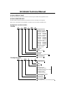
I-3 LIST OF PINS.................................................................................................................B-I-3-1
List of External I/O Pins...............................................................................................................B-I-3-1
II CORE BLOCK
II-1 INTRODUCTION ........................................................................................................... B-II-1-1
II-2 CPU AND OPERATING MODE ................................................................................... B-II-2-1
CPU ............................................................................................................................................B-II-2-1
Standby Mode.............................................................................................................................B-II-2-2
HALT Mode.....................................................................................................................B-II-2-2
SLEEP Mode ..................................................................................................................B-II-2-2
Notes on Standby Mode .................................................................................................B-II-2-3
Test Mode ...................................................................................................................................B-II-2-3
Debug Mode ...............................................................................................................................B-II-2-3
Trap Table...................................................................................................................................B-II-2-4
II-3 INITIAL RESET ............................................................................................................. B-II-3-1
Pins for Initial Reset....................................................................................................................B-II-3-1
Cold Start and Hot Start .............................................................................................................B-II-3-1
Power-on Reset..........................................................................................................................B-II-3-2
Reset Pulse.................................................................................................................................B-II-3-2
Boot Address ..............................................................................................................................B-II-3-3
Notes Related to Initial Reset.....................................................................................................B-II-3-3
II-4 BCU (Bus Control Unit)............................................................................................... B-II-4-1
Pin Assignment for External System Interface..........................................................................B-II-4-1
I/O Pin List.......................................................................................................................B-II-4-1
Combination of System Bus Control Signals.................................................................B-II-4-3
Memory Area ..............................................................................................................................B-II-4-4
Memory Map ................................................................................................................... B-II-4-4
External Memory Map and Chip Enable ........................................................................B-II-4-5
Using Internal Memory on External Memory Area.........................................................B-II-4-7
Exclusive Signals for Areas............................................................................................ B-II-4-7
Area 10............................................................................................................................B-II-4-8
Area 3..............................................................................................................................B-II-4-9
Setting External Bus Conditions ..............................................................................................B-II-4-10
Setting Device Type and Size ......................................................................................B-II-4-10
Setting SRAM Timing Conditions.................................................................................B-II-4-11
Setting Timing Conditions of Burst ROM.....................................................................B-II-4-12
Bus Operation...........................................................................................................................B-II-4-13
Data Arrangement in Memory ......................................................................................B-II-4-13
Bus Operation of External Memory..............................................................................B-II-4-13