


2 POWER SUPPLY
A-12 EPSON S1C33L03 PRODUCT PART
2 Power Supply
This chapter explains the operating voltage of the S1C33L03.
2.1 Power Supply Pins
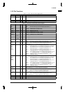
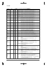
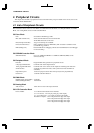
The S1C33L03 has the power supply pins shown in Table 2.1.1.
Table 2.1.1 Power Supply Pins
Pin name Pin No. Function
VDD 8,51,78,127 Power supply (+) for the internal logic
VSS 3,27,45,66,82,98,105,114,116,136Power supply (-); GND
VDDE 21,59,91,132 Power supply (+) for the I/O block
AVDDE 36 Analog system power supply (+); AVDDE = VDDE
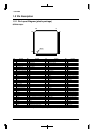
I/O
interface circuit
CPU core
Internal
peripheral
circuit
V
DD
1.8 to 3.6 V
1.8 to 5.5 V
1.8 to 5.5 V
GND
V
DDE
I/O pins
Analog circuits
(A/D converter)
AV
DDE
V
SS
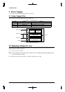
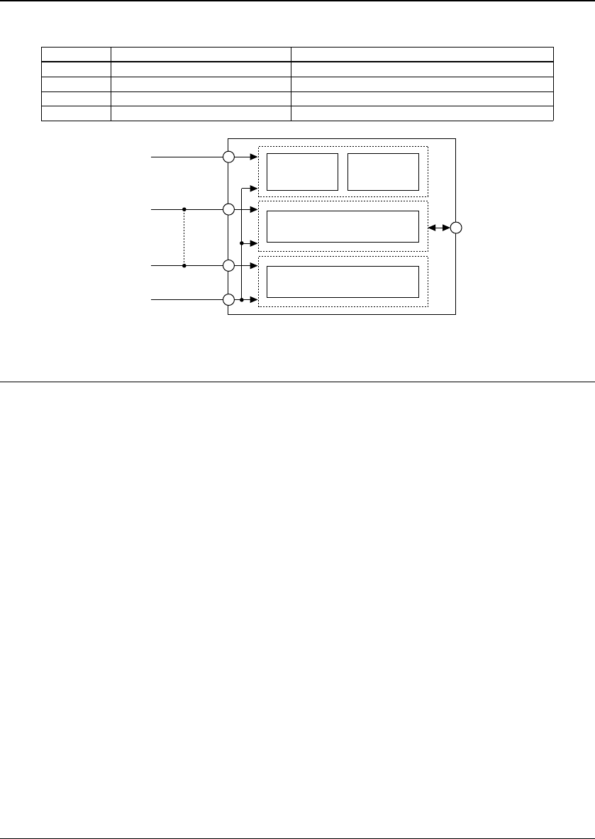
Figure 2.1.1 Power Supply System
2.2 Operating Voltage (VDD, VSS)
The core CPU and internal peripheral circuits operate with a voltage supplied between the VDD and VSS pins. The
following operating voltage can be used:
V
DD = 1.8 V to 3.6 V (VSS = GND)
Note: The S1C33L03 has 4 V
DD pins and 10 VSS pins. Be sure to supply the operating voltage to all the
pins. Do not open any of them.
The operating clock frequency range (OSC3) is 5 MHz to 50 MHz with this voltage.