


II CORE BLOCK: CLG (Clock Generator)
B-II-6-2 EPSON S1C33L03 FUNCTION PART
I/O Pins of Clock Generator
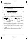
Table 6.1 lists the I/O pins of the clock generator.
Table 6.1 I/O Pins of Clock Generator
Pin name I/O Function
OSC3 I High-speed (OSC3) oscillation input pin
Crystal/ceramic oscillation or external clock input
OSC4 O High-speed (OSC3) oscillation output pin
Crystal/ceramic oscillation (open when external clock is used)
PLLC – Capasitor connecting pin for PLL
PLLS[1:0] I PLL set-up pins
PLLS1 PLLS0 fin (fOSC3)fout (fPSCIN)
1110–25MHz 20–50MHz ∗1
0110–12.5MHz 40–50MHz ∗1
00PLL is not used L ∗2
∗1: ROM-less model with 3.3 V ± 0.3 V operating voltage
∗2: When the PLL is not used, the OSC3 clock is used directly.
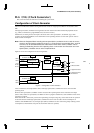
High-Speed (OSC3) Oscillation Circuit
The high-speed (OSC3) oscillation circuit generates the main clock for the CPU and internal peripheral circuits
(e.g., DMA, serial interface, programmable timer, and A/D converter).
This circuit can be a crystal or a ceramic oscillation circuit. Optionally an external clock source can be used.
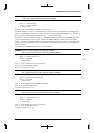
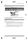
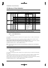
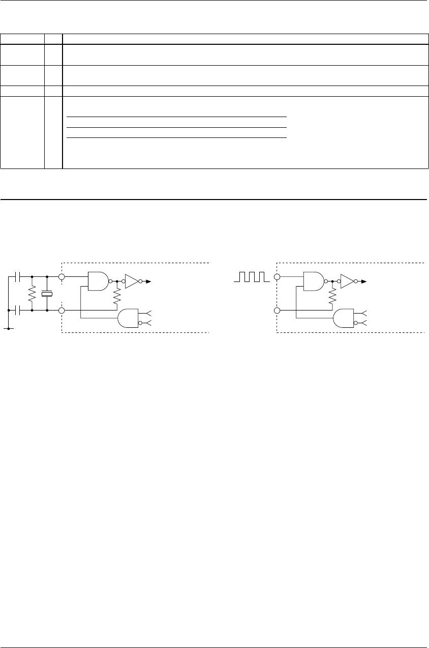
Figure 6.2 shows the structure of the high-speed (OSC3) oscillation circuit.
V
SS
OSC4
OSC3
R
f
C
D2
C
G2
Oscillation circuit
control signal
SLEEP status
Oscillation circuit
control signal
SLEEP status
X'tal2
or
Ceramic
f
OSC3
OSC4
OSC3
External
clock
N.C.
V
SS
V
DD
f
OSC3
(
1
)
Cr
y
stal/ceramic oscillation circuit
(
2
)
External clock in
p
ut
Figure 6.2 High-Speed (OSC3) Oscillation Circuit
When using a crystal or a ceramic oscillation for this circuit, connect a crystal (X'tal2) or ceramic (Ceramic)
resonator and feedback resistor (Rf) between the OSC3 and OSC4 pins, and two capacitors (C
G2, CD2) between the
OSC3 pin and V
SS and the OSC4 pin and VSS, respectively.
When an external clock is used, leave the OSC4 pin open and input a square-wave clock to the OSC3 pin.
The range of oscillation frequencies is 10 MHz to 33 MHz. This frequency range also applies when an external
clock is used.
Note: When using the PLL, the oscillation frequency range changes according to the PLL setting. See
Table 6.2.
For details on oscillation characteristics and the external clock input characteristics, refer to "Electrical
Characteristics".