


II CORE BLOCK: ITC (Interrupt Controller)
S1C33L03 FUNCTION PART EPSON B-II-5-1
A-1
B-II
ITC
II-5 ITC (Interrupt Controller)
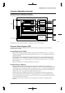
The C33 Core Block contains an interrupt controller, making it possible to control all interrupts generated by
the internal peripheral circuits. This section explains the functions of this interrupt controller centering around the
method for controlling maskable interrupts. For details about the various factors and conditions under which
interrupts are generated, refer to the description of each peripheral circuit in this manual.
Outline of Interrupt Functions
Maskable Interrupts
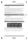
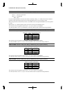
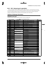
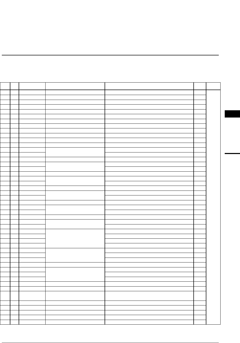
The ITC can handle 39 kinds of maskable interrupts as shown in the table below.
Table 5.1 List of Maskable Interrupts
No
.
HE
X
No
.
Vector numbe
r
(Hex address
)
Interrupt system
(Peripheral circuit)
Interrupt factor
IDMA
Ch.
Priorit
y
11016(Base+40) Port input interrupt 0 Edge (rising or falling) or level (High or Low) 1 High
21117(Base+44) Port input interrupt 1 Edge (rising or falling) or level (High or Low) 2
↑
31218(Base+48) Port input interrupt 2 Edge (rising or falling) or level (High or Low) 3
41319(Base+4C) Port input interrupt 3 Edge (rising or falling) or level (High or Low) 4
51420(Base+50) Key input interrupt 0 Rising or falling edge –
61521(Base+54) Key input interrupt 1 Rising or falling edge –
71622(Base+58) High-speed DMA Ch.0 High-speed DMA Ch.0, end of transfer 5
81723(Base+5C) High-speed DMA Ch.1 High-speed DMA Ch.1, end of transfer 6
91824(Base+60) High-speed DMA Ch.2 High-speed DMA Ch.2, end of transfer –
10 19 25(Base+64) High-speed DMA Ch.3 High-speed DMA Ch.3, end of transfer –
11 1A 26(Base+68) IDMA Intelligent DMA, end of transfer –
– 27–29 reserved – –
12 1E 30(Base+78) 16-bit programmable timer 0 Timer 0 comparison B 7
13 1F 31(Base+7C) Timer 0 comparison A 8
– 32–33 reserved – –
14 22 34(Base+88) 16-bit programmable timer 1 Timer 1 comparison B 9
15 23 35(Base+8C) Timer 1 comparison A 10
– 36–37 reserved – –
16 26 38(Base+98) 16-bit programmable timer 2 Timer 2 comparison B 11
17 27 39(Base+9C) Timer 2 comparison A 12
– 40–41 reserved – –
18 2A 42(Base+A8) 16-bit programmable timer 3 Timer 3 comparison B 13
19 2B 43(Base+AC) Timer 3 comparison A 14
– 44–45 reserved – –
20 2E 46(Base+B8) 16-bit programmable timer 4 Timer 4 comparison B 15
21 2F 47(Base+BC) Timer 4 comparison A 16
– 48–49 reserved – –
22 32 50(Base+C8) 16-bit programmable timer 5 Timer 5 comparison B 17
23 33 51(Base+CC) Timer 5 comparison A 18
24 34 52(Base+D0) 8-bit programmable timer Timer 0 underflow 19
25 35 53(Base+D4) Timer 1 underflow 20
26 36 54(Base+D8) Timer 2 underflow 21
27 37 55(Base+DC) Timer 3 underflow 22
28 38 56(Base+E0) Serial interface Ch.0 Receive error –
29 39 57(Base+E4) Receive buffer full 23
30 3A 58(Base+E8) Transmit buffer empty 24
–59 reserved – –
31 3C 60(Base+F0) Serial interface Ch.1 Receive error –
32 3D 61(Base+F4) Receive buffer full 25
33 3E 62(Base+F8) Transmit buffer empty 26
–63 reserved – –
34 40 64(Base+100) A/D converter A/D converter, end of conversion 27
35 41 65(Base+104) Clock timer Falling edge of 32 Hz, 8 Hz, 2 Hz or 1 Hz signal
1-minuet, 1-hour or specified time count up
–
– 66–67 reserved – –
36 44 68(Base+110) Port input interrupt 4 Edge (rising or falling) or level (High or Low) 28
37 45 69(Base+114) Port input interrupt 5 Edge (rising or falling) or level (High or Low) 29
38 46 70(Base+118) Port input interrupt 6 Edge (rising or falling) or level (High or Low) 30
↓
39 47 71(Base+11C
)
Port input interrupt 7 Edge (rising or falling) or level (High or Low) 31 Low