VII LCD CONTROLLER BLOCK: LCD CONTROLLER
S1C33L03 FUNCTION PART EPSON B-VII-2-23
A-1
B-VII
LCDC
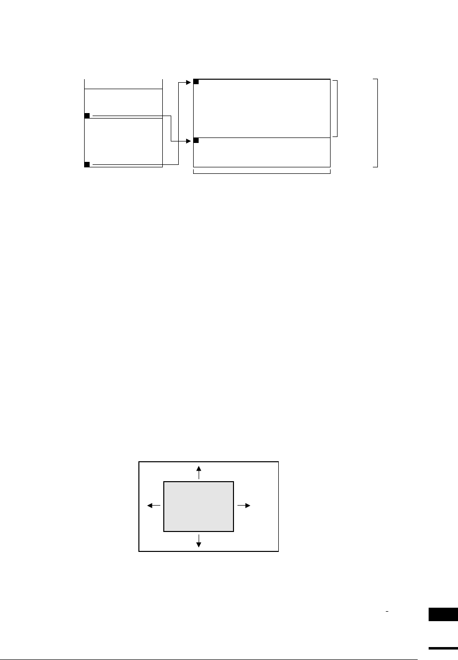
Split-Screen Display
The LCD controller supports a split-screen function, allowing different images to be displayed on two vertically
split screens on the LCD panel. To discriminate between these two screens, the upper half of the LCD panel is
referred to as "screen 1" and the lower half is referred to as "screen 2".
Screen 1 data
Screen 2 data
Screen 1 start address
Screen 2 start address
Display memory LCD panel
Screen 1
Screen 2
S1VSIZE
+ 1 (lines)
LDVSIZE
+ 1 (lines)
(LDHSIZE + 1) × 16 (pixels)
Figure 2.16 Split-Screen Display
A register similar to the screen 1 start address register described above is provided; it is called the "screen 2 start
address register (0x39FFEE, 0x39FFEF)". Use this register to set the start address of screen 2. In the initial state,
the start address of screen 2 is set to 0x0, as with screen 1.
Use the number of lines on screen 1 to specify the position at which to divide between the two screens. To evenly
split an LCD panel with 240 lines of vertical resolution into upper and lower halves, for example, set the value 119
in S1VSIZE[9:0] (D[9:0])/screen 1 vertical size register (0x39FFF3, 0x39FFF2). The LCD panel is separated into
screen 1 consisting of lines 0–119, and screen 2 consisting of lines 120–239.
In the initial state, S1VSIZE[9:0] is set to 0. As a result, screen 1 is nonexistent and screen 2 is displayed over the
entire panel.
To display only screen 1, set the same value in S1VSIZE[9:0] as that set in the LDVSIZE[9:0] (D[9:0])/vertical
panel size register (0x39FFE6, 0x39FFE5). The entire screen can be changed instantaneously to different images
by switching between S1VSIZE = LDVSIZE and S1VSIZE = 0.
Virtual Screen and View Port
The LCD controller has a virtual-screen function that allows any necessary portion of the screen to be displayed
through panning or scrolling, by holding in memory than that required to achieve the resolution. However, because
a virtual screen is configured within the display memory, it is limited in size to a maximum of 256K bytes. The
area corresponding to the actual LCD panel size is referred to as a view port, and can be relocated within the virtual
screen by changing the display start address.
Virtual screen
View port
(LCD panel size)
Figure 2.17 Virtual Screen and View Port
The procedure for setting a virtual screen and panning or scrolling the view port is explained below, assuming that
screen 1 is used.
Because the view port than that required to achieve the resolution size is equal to that required to achieve the
resolution of the LCD panel, the values set in the horizontal panel size register (0x39FFE4) and vertical panel size
register (0x39FFE6, 0x39FFE5) are applied directly as they are.


