


III PERIPHERAL BLOCK: SERIAL INTERFACE
S1C33L03 FUNCTION PART EPSON B-III-8-25
A-1
B-III
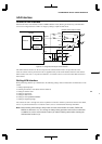
SIF
The interrupt priority register sets the interrupt priority level of each interrupt source in a range between 0 and
7. An interrupt request to the CPU is accepted only when no other interrupt request of a higher priority has
been generated.
In addition, only when the PSR's IE bit = "1" (interrupts enabled) and the set value of the IL is smaller than
the input interrupt level set by the interrupt priority register, will the input interrupt request actually be
accepted by the CPU.
For details on these interrupt control registers, as well as the device operation when an interrupt has occurred,
refer to "ITC (Interrupt Controller)".
•Ch.2 and Ch.3
Ch.2 and Ch.3 do not have dedicated interrupt signals. Either a port input interrupt or 16-bit timer interrupt is
selected, and interrupt handling is performed accordingly.
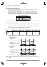
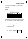
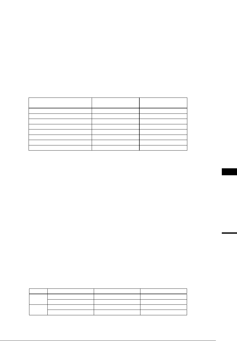
The correspondence between port input interrupt factors and 16-bit timer interrupt factors is shown in
Table.8.10.
Table 8.10 Correspondence between Interrupt Factors
Serial I/F Ch.2, Ch.3/
T8-Ch.4, Ch.5 interrupt factor
Port input interrupt
factor
16-bit timer interrupt
factor
T8 Ch.5 UF FPT7 Timer 2 compare A
T8 Ch.4 UF FPT5 Timer 2 compare B
SIO Ch.3 TXD Emp. FPT6 Timer 4 compare A
SIO Ch.3 RXD Full FPT4 Timer 4 compare B
SIO Ch.3 RXD Err. FPT2 Timer 3 compare A
SIO Ch.2 TXD Emp. FPT3 Timer 5 compare A
SIO Ch.2 RXD Full FPT1 Timer 5 compare B
SIO Ch.2 RXD Err. FPT0 Timer 3 compare B
Switching between the above interrupt factors is performed by means of the interrupt factor FP function
switching register (0x402C5) and the interrupt factor TM16 function switching register (0x402CB).
For the setting of the interrupt controller in the CPU-core, the setting for the selected interrupt factor is used.
Refer to "ITC (Interrupt Controller)" in the Core Block section for details of interrupts, and "Input/Output
Ports" and "16-Bit Programmable Timers" in the Peripheral Block section for details of port input interrupt
factor and 16-bit timer interrupt factor settings.
Intelligent DMA
•Ch.0 and Ch.1
The receive-buffer full interrupt and transmit-buffer empty interrupt factors can be used to invoke intelligent
DMA (IDMA). This enables successive transmit/receive operations between memory and the
transmit/receive-buffer to be performed by means of a DAM transfer.
The following shows the IDMA channel numbers set for each interrupt factor:
IDMA Ch.
Ch.0 receive-buffer full interrupt: 0x17
Ch.0 transmit-buffer empty interrupt: 0x18
Ch.1 receive-buffer full interrupt: 0x19
Ch.1 transmit-buffer empty interrupt: 0x1A
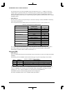
The IDMA request and enable bits shown in Table 8.11 must be set to "1" for IDMA to be invoked. Transfer
conditions, etc. on the IDMA side must also be set in advance.
Table 8.11 Control Bits for IDMA Transfer
Channel Interrupt factor IDMA request bit IDMA enable bit
Ch.0 Receive-buffer full RSRX0(D6/0x40292) DESRX0(D6/0x40296)
Transmit-buffer empty RSTX0(D7/0x40292) DESTX0(D7/0x40296)
Ch.1 Receive-buffer full RSRX1(D0/0x40293) DESRX1(D0/0x40297)
Transmit-buffer empty RSTX1(D1/0x40293) DESTX1(D1/0x40297)