


V DMA BLOCK: HSDMA (High-Speed DMA)
S1C33L03 FUNCTION PART EPSON B-V-2-31
A-1
B-V
HSDMA
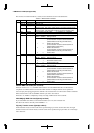
D0MOD1–D0MOD0: Ch. 0 transfer mode (D[F:E]) / Ch. 0 high-order destination address set-up register (0x4822A)
D1MOD1–D1MOD0: Ch. 1 transfer mode (D[F:E]) / Ch. 1 high-order destination address set-up register (0x4823A)
D2MOD1–D2MOD0: Ch. 2 transfer mode (D[F:E]) / Ch. 2 high-order destination address set-up register (0x4824A)
D3MOD1–D3MOD0: Ch. 3 transfer mode (D[F:E]) / Ch. 3 high-order destination address set-up register (0x4825A)
Select a transfer mode.
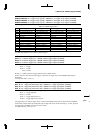
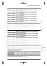
Table 2.7 Transfer Mode
DxMOD1 DxMOD0 Mode
11Invalid
10Block transfer mode
01Successive transfer mode
00Single transfer mode
In single transfer mode, a transfer operation invoked by one trigger is completed after transferring one unit of data
of the size set by DATSIZEx.
In successive transfer mode, data transfer operations are performed by one trigger a number of times as set by the
transfer counter.
In block transfer mode, a transfer operation invoked by one trigger is completed after transferring one block of data
of the size set by BLKLENx.
At initial reset, DxMOD is set to "00" (single transfer mode).
DATSIZE0: Ch. 0 transfer data size (DE) / Ch. 0 high-order source address register (0x48226)
DATSIZE1: Ch. 1 transfer data size (DE) / Ch. 1 high-order source address register (0x48236)
DATSIZE2: Ch. 2 transfer data size (DE) / Ch. 2 high-order source address register (0x48246)
DATSIZE3: Ch. 3 transfer data size (DE) / Ch. 3 high-order source address register (0x48256)
Select the data size to be transferred.
Write "1": Half-word (16 bits)
Write "0": Byte (8 bits)
Read: Valid
The transfer data size is set to 16 bits by writing "1" to DATSIZEx and set to 8 bits by writing "0".
At initial reset, DATSIZEx is set to "0" (8 bits).
S0IN1–S0IN0:
Ch. 0 source address control (D[D:C]) / Ch. 0 high-order source address set-up register (0x48226)
S1IN1–S1IN0: Ch. 1 source address control (D[D:C]) / Ch. 1 high-order source address set-up register (0x48236)
S2IN1–S2IN0: Ch. 2 source address control (D[D:C]) / Ch. 2 high-order source address set-up register (0x48246)
S3IN1–S3IN0: Ch. 3 source address control (D[D:C]) / Ch. 3 high-order source address set-up register (0x48256)
Control the incrementing or decrementing of the memory address.
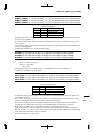
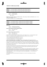
Table 2.8 Address Control
SxIN1 SxIN0 Address control
11Increment without initialization
10Increment with initialization
01Decrement without initialization
00Fixed
In dual-address mode, this setting applies to the source address. In single-address mode, this setting applies to the
external memory address.
When "address fixed" (00) is selected, the source address is not changed by a data transfer performed. Even when
transferring multiple data, the transfer data is always read from the same address.
When "address increment" (11 or 10) is selected in single and successive transfer modes, the source address is
incremented by an amount equal to the data size set by DATSIZEx when one data transfer is completed.
When "address decrement" (01) is selected, the source address is decremented in the same way.
In block transfer mode too, the source address is incremented or decremented when one data unit is transferred.
However, if SxIN is set to "10", the source address that has been incremented during a block transfer recycles back
to the initial value when the block transfer is completed.
At initial reset, SxIN is set to "00" (Fixed).