


III PERIPHERAL BLOCK: SERIAL INTERFACE
B-III-8-22 EPSON S1C33L03 FUNCTION PART
Selecting the IrDA interface function
To use the IrDA interface function, select it using the control bits shown below and then set the 8-bit (or 7-
bit) asynchronous mode as the transfer mode.
Ch.0 IrDA interface-function selection: IRMD0[1:0] (D[1:0]) / Serial I/F Ch.0 IrDA register (0x401E4)
Ch.1 IrDA interface-function selection: IRMD1[1:0] (D[1:0]) / Serial I/F Ch.1 IrDA register (0x401E9)
Ch.2 IrDA interface-function selection: IRMD2[1:0] (D[1:0]) / Serial I/F Ch.2 IrDA register (0x401F4)
Ch.3 IrDA interface-function selection: IRMD3[1:0] (D[1:0]) / Serial I/F Ch.3 IrDA register (0x401F9)
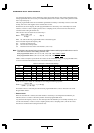
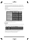
Table 8.7 Setting of IrDA Interface
IRMDx1 IRMDx0 Interface mode
11Do not set. (reserved)
10IrDA 1.0 interface
01Do not set. (reserved)
00Normal interface
Note: The IRMDx bit becomes indeterminate when initially reset, so be sure to initialize it in the software.
Setting the input/output logic
When using the IrDA interface, the logic of the input/output signals of the PPM modulator circuit can be
changed in accordance with the infrared-ray communication module or the circuit connected externally to the
chip. The logic of the internal serial interface is "active-low". If the input/output signals are active-high, the
logic of these signals must be inverted before they can be used. The input SINx and output SOUTx logic can
be set individually through the use of the IRRLx and IRTLx bits, respectively.
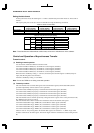
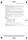
Table 8.8 IrDA Input/Output Logic Inversion Bits
Ch.0 (Serial I/F Ch.0
control register)
Ch.1 (Serial I/F Ch.1
control register)
Ch.2 (Serial I/F Ch.2
control register)
Ch.3 (Serial I/F Ch.3
control register)
IrDA input logic
inversion
IRRL0(D2/0x401E4) IRRL1(D2/0x401E9) IRRL2(D2/0x401F4) IRRL3(D2/0x401F9)
IrDA output logic
inversion
IRTL0(D3/0x401E4) IRTL1(D3/0x401E9) IRTL2(D3/0x401F4) IRTL3(D3/0x401F9)
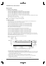
The logic of the input/output signal is inverted by writing "1" to each corresponding bit. Logic is not inverted
if the bit is set to "0".
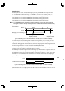
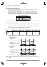
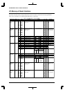
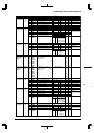
PPM modulator input (I/F output)
PPM modulator output (SOUTx)
(1) IRTLx = "0"
When transmitting
PPM modulator input (I/F output)
PPM modulator output (SOUTx)
(2) IRTLx = "1"
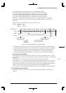
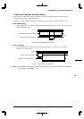
PPM modulator input (SINx)
PPM modulator output (I/F input)
(1) IRRLx = "0"
When receiving
PPM modulator input (SINx)
PPM modulator output (I/F input)
(2) IRRLx = "1"
Figure 8.15 IRRLx and IRTLx Settings
Note: The IRRLx and IRTLx bits become indeterminate at initial reset, so be sure to initialize them in the
software.