


IV ANALOG BLOCK: A/D CONVERTER
S1C33L03 FUNCTION PART EPSON B-IV-2-1
A-1
B-IV
A/D
IV-2 A/D CONVERTER
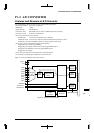
Features and Structure of A/D Converter
The Analog Block contains an A/D converter with the following features:
•Conversion method: Successive comparison
•Resolution: 10 bits
•Input channels: Maximum of 8
•Conversion time: Maximum of 10 µs (when a 2-MHz input clock is selected)
•Conversion range: Between V
SS and AVDDE
•Two conversion modes can be selected:
Normal mode: Conversion is completed in one operation.
Continuous mode: Conversion is continuous and terminated through software control.
Continuous conversion of multiple channels can be performed in each mode.
•Four types of A/D-conversion start triggers can be selected:
Triggered by the external pin (#ADTRG)
Triggered by the compare match B of the 16-bit programmable timer 0
Triggered by the underflow of the 8-bit programmable timer 0
Triggered by the software
•A/D conversion results can be read out from a 10-bit data register.
•An interrupt is generated upon completion of A/D conversion.
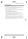
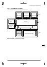
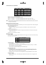
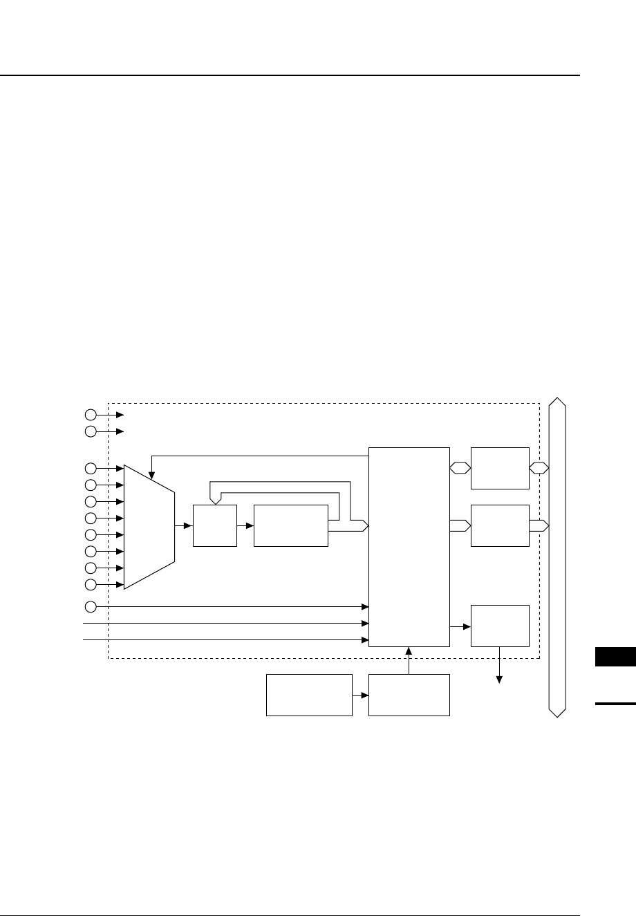
Figure 2.1 shows the structure of the A/D converter.
Internal data bus
AV
DDE
V
SS
Analog
input
decoder
Control circuit
AD0
AD1
AD2
AD3
AD4
AD5
AD6
AD7
#ADTRG
8-bit timer 0
16-bit timer 0
Clock
generator
Prescaler
Interrupt request
Analog
block
Successive
approximation
block
Data
register
Interrupt
control
circuit
Control
registers
Figure 2.1 Structure of A/D Converter