


VII LCD CONTROLLER BLOCK: LCD CONTROLLER
S1C33L03 FUNCTION PART EPSON B-VII-2-35
A-1
B-VII
LCDC
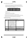
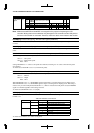
BPP[1:0]: Bit-per-pixel select (D[7:6]) / LCDC mode register 1 (0x39FFE2)
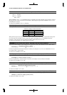
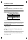
Selects display mode (bpp mode). The contents of selection, including that of LDCOLOR, are listed in Table 2.23.
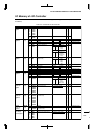
Table 2.23 Specification of Display Modes
LDCOLOR BPP1 BPP0 Display mode
02 gray scale 1 bit-per-pixel0
14 gray scale 2 bit-per-pixel
016 gray scale 4 bit-per-pixel
0
1
1Reserved
02 colors 1 bit-per-pixel0
14 colors 2 bit-per-pixel
016 colors 4 bit-per-pixel
1
1
1256 colors 8 bit-per-pixel
At initial reset, BPP is set to "0b00" (1-bpp mode).
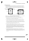
DBLANK: Blank display (D3) / LCDC mode register 1 (0x39FFE2)
Clears the display (entire screen turned black).
Write "1": Blank
Write "0": Normal display
Read: Valid
When DBLANK is set to "1", all FPDAT signals are dropped low to clear the display. When DBLANK is set to
"0", data in the display memory is displayed on the LCD panel. This setting does not affect the display memory.
At initial reset, DBLANK is set to "0" (normal display).
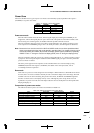
FRMRPT: Frame repeat for EL panel (D2) / LCDC mode register 1 (0x39FFE2)
Selects whether to repeat the frame-rate modulation pattern (effective only for EL panels).
Write "1": Repeated
Write "0": Not repeated
Read: Valid
When FRMRPT is set to "1", the internal 19-bit frame counter is enabled and starts counting the number of frames.
Each time this counter overflows (0x40000 = 0), the frame-rate modulation pattern is repeated. When FRMRPT is
set to "0", the counter is disabled and the frame-rate modulation pattern is not repeated.
At initial reset, FRMRPT is set to "0" (not repeated).
INVDISP: Invert display (D0) / LCDC mode register 1 (0x39FFE2)
Inverts the display.
Write "1": Inverted
Write "0": Normal display
Read: Valid
When INVDISP is set to "1", the display on the LCD panel is inverted (displayed in inverse video). When
INVDISP is set to "0", normal display is maintained. Invers operation is applied to output of the look-up tables,
and does not affect the display memory.
At initial reset, INVDISP is set to "0" (normal display).
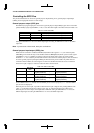
LCDCEN: Enable LCDC (D5) / LCDC mode register 2 (0x39FFE3)
Enables the LCD controller for use.
Write "1": Enabled
Write "0": Disabled
Read: Valid
When LCDCEN is set to "1", the LCD controller is supplied with a clock and starts operating. When LCDCEN is
set to "0", the LCD controller stops operating. Note that if the power to the LCD panel turns on while LCD signals
are not output correctly, the LCD panel may be degraded or damaged.
At initial reset, LCDCEN is set to "0" (disabled).