


IV ANALOG BLOCK: A/D CONVERTER
B-IV-2-4 EPSON S1C33L03 FUNCTION PART
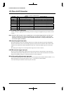
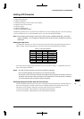
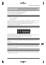
Table 2.3 Relationship between CS/CE and Input Channel
CS2/CE2 CS1/CE1 CS0/CE0 Channel selected
11 1 AD7
11 0 AD6
10 1 AD5
10 0 AD4
01 1 AD3
01 0 AD2
00 1 AD1
00 0 AD0
Example: Operation of one A/D conversion
CS[2:0] = "0", CE[2:0] = "0": Converted only in AD0
CS[2:0] = "0", CE[2:0] = "3": Converted in the following order: AD0→AD1→AD2→AD3
CS[2:0] = "5", CE[2:0] = "1": Converted in the following order: AD5→AD6→AD7→AD0→AD1
Note: Only conversion-channel input pins that have been set for use with the A/D converter can be set
using the CS and CE bits.
Setting the A/D conversion mode
The A/D converter can operate in one of the following two modes. This operation mode is selected using MS
(D5) / A/D trigger register (0x40242).
1. Normal mode (MS = "0")
All inputs in the range of channels set using the CS and CE bits are A/D converted once and then
stopped.
2. Continuous mode (MS = "1")
A/D conversions in the range of channels set using the CS and CE bits are executed successively until
stopped by the software.
At initial reset, the normal mode is selected.
Selecting a trigger
Use TS[1:0] (D[4:3]) / A/D trigger register (0x40242) to select a trigger to start A/D conversion from among
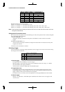
the four types shown in Table 2.4.
Table 2.4 Trigger Selection
TS1 TS0 Trigger
11External trigger (K52/#ADTRG)
108-bit programmable timer 0
0116-bit programmable timer 0
00Software
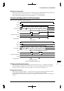
1. External trigger
The signal input to the #ADTRG pin is used as a trigger.
When this trigger is used, the K52 pin must be set for #ADTRG in advance by writing "1" to CFK52
(D2) / K5 function select register (0x402C0).
A/D conversion is started at a falling edge of the #ADTRG signal.
2. Programmable timer
The underflow signal of 8-bit programmable timer 0 or the comarison match B signal of the 16-bit
programmable timer 0 is used as a trigger. Since the cycle can be programmed using each timer, this
trigger is effective when cyclic A/D conversions are required.
For details on how to set a timer, refer to the explanation of each programmable timer in this manual.
3. Software trigger
Writing "1" to ADST (D1) / A/D enable register (0x40244) in the software serves as a trigger to start
A/D conversion.