III PERIPHERAL BLOCK: SERIAL INTERFACE
B-III-8-40 EPSON S1C33L03 FUNCTION PART
IRTL0: Ch.0 IrDA output logic inversion (D3) / Serial I/F Ch.0 IrDA register (0x401E4)
IRTL1: Ch.1 IrDA output logic inversion (D3) / Serial I/F Ch.1 IrDA register (0x401E9)
IRTL2: Ch.2 IrDA output logic inversion (D3) / Serial I/F Ch.2 IrDA register (0x401F4)
IRTL3: Ch.3 IrDA output logic inversion (D3) / Serial I/F Ch.3 IrDA register (0x401F9)
Inverts the logic of the IrDA output signal.
Write "1": Inverted
Write "0": Not inverted
Read: Valid
When using the IrDA interface, set the logic of the SOUTx output signal to suit the infrared-ray communication
circuit that is connected external to the chip. If IRTLx is set to "1", a high pulse is output when the output data =
"0" (held low-level when the output data = "1"). If IRTLx is set to "0", a low pulse is output when the output data =
"0" (held high-level when the output data = "1").
At initial reset, IRTLx becomes indeterminate.
IRRL0: Ch.0 IrDA input logic inversion (D2) / Serial I/F Ch.0 IrDA register (0x401E4)
IRRL1: Ch.1 IrDA input logic inversion (D2) / Serial I/F Ch.1 IrDA register (0x401E9)
IRRL2: Ch.2 IrDA input logic inversion (D2) / Serial I/F Ch.2 IrDA register (0x401F4)
IRRL3: Ch.3 IrDA input logic inversion (D2) / Serial I/F Ch.3 IrDA register (0x401F9)
Inverts the logic of the IrDA input signal.
Write "1": Inverted
Write "0": Not inverted
Read: Valid
When using the IrDA interface, set the logic of the signal that is input from an external infrared-ray communication
circuit to the chip to suit the serial interface. If IRRLx is set to "1", a high pulse is input as a logic "0". If IRRLx is
set to "0", a low pulse is input as a logic "0".
At initial reset, IRRLx becomes indeterminate.
IRMD01–IRMD00: Ch.0 IrDA interface mode selection (D[1:0]) / Serial I/F Ch.0 IrDA register (0x401E4)
IRMD11–IRMD10: Ch.1 IrDA interface mode selection (D[1:0]) / Serial I/F Ch.1 IrDA register (0x401E9)
IRMD21–IRMD20: Ch.2 IrDA interface mode selection (D[1:0]) / Serial I/F Ch.2 IrDA register (0x401F4)
IRMD31–IRMD30: Ch.3 IrDA interface mode selection (D[1:0]) / Serial I/F Ch.3 IrDA register (0x401F9)
Selects the IrDA interface function.
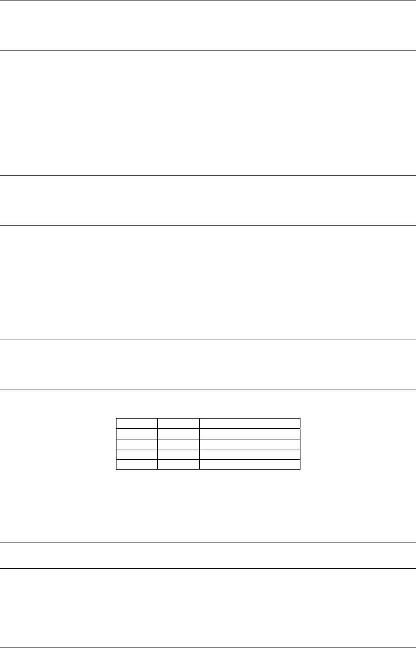
Table 8.16 IrDA Interface Setting
IRMDx1 IRMDx0 Interface mode
11Do not set. (reserved)
10IrDA 1.0 interface
01Do not set. (reserved)
00Normal interface
When using the IrDA interface function, write "10" to IRMDx while setting to an asynchronous mode for the
transfer mode. If the IrDA interface function is not to be used, write "00" to IRMDx.
At initial reset, IRMDx becomes indeterminate.
Note: This selection must always be performed before the transfer mode and other conditions are set.
PSIO02–PSIO00:
Ch.0 interrupt level (D[6:4]) / 8-bit timer, serial I/F Ch.0 interrupt priority register (0x40269)
PSIO12–PSIO10: Ch.1 interrupt level (D[2:0]) / Serial I/F Ch.1, A/D interrupt priority register (0x4026A)
Sets the priority level of the serial-interface interrupt.
The interrupt priority level can be set for each channel in the range of 0 to 7.
At initial reset, PSIOx becomes indeterminate.


