


III PERIPHERAL BLOCK: INPUT/OUTPUT PORTS
B-III-9-12 EPSON S1C33L03 FUNCTION PART
Input Interrupt
The input ports and the I/O ports support eight system of port input interrupts and two systems of key input
interrupts.
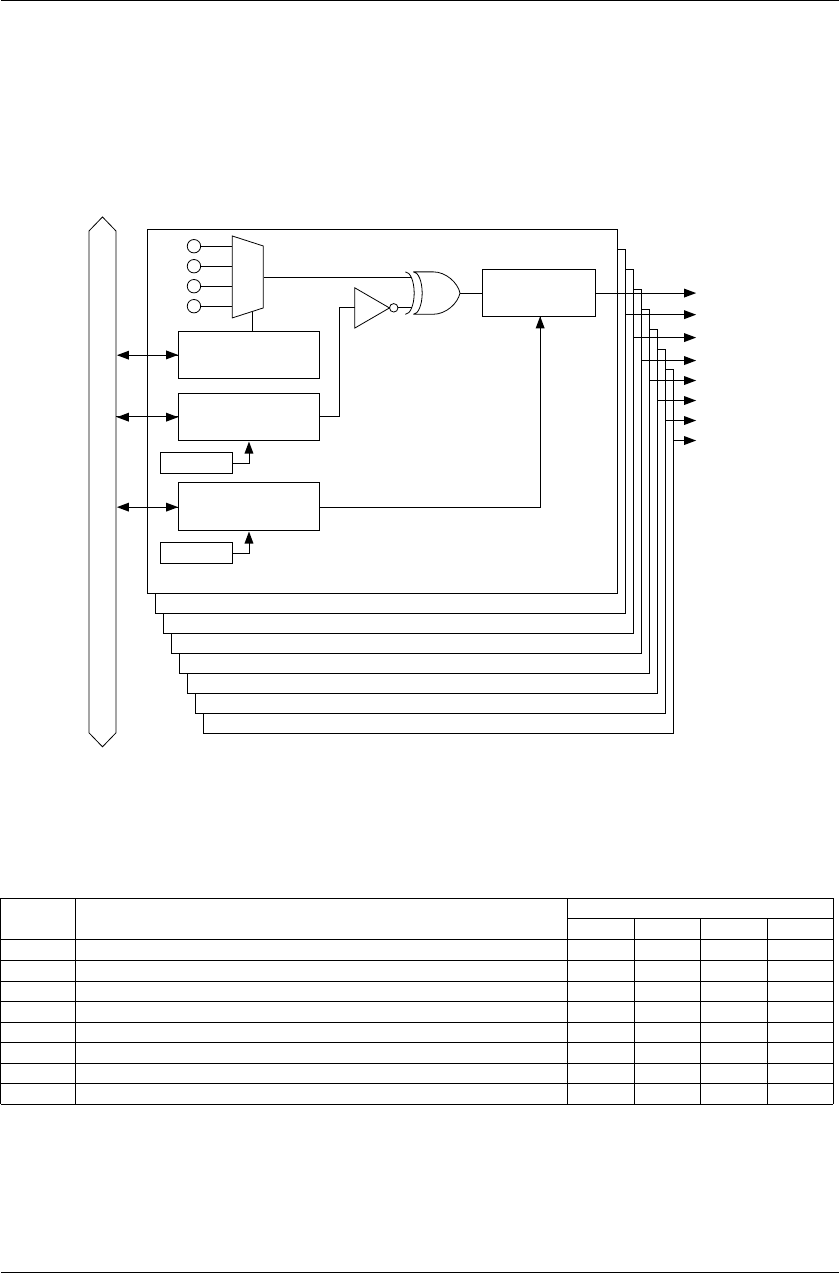
Port Input Interrupt
The port input interrupt circuit has eight interrupt systems (FPT7–FPT0) and a port can be selected for generating
each interrupt factor.
The interrupt condition can also be selected from between input signal edge and input signal level.
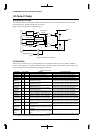
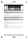
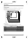
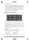
Figure 9.3 shows the configuration of the port input interrupt circuit.
FPT0
FPT1
FPT2
Internal data bus
FPT3
FPT4
FPT5
K67
P33
P07
P27
Input polarity
selection SPPT7
Edge/level
selection SEPT7
Address
Address
FPT6
FPT7
FPT7
FPT6
FPT5
FPT4
FPT3
FPT2
FPT1
FPT0
Input port selection
SPT7
Interrupt
request
Interrupt signal
generation
Figure 9.3 Configuration of Port Input Interrupt Circuit
Selecting input pins
The interrupt factors allows selection of an input pin from the four predefined pins independently.
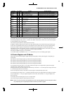
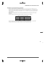
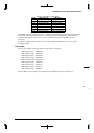
Table 9.5 shows the control bits and the selectable pins for each factor.
Table 9.5 Selecting Pins for Port Input Interrupts
Interrupt SPT settings
factor
Control bit
11 10 01 00
FPT7 SPT7[1:0] (D[7:6])/Port input interrupt select register 2 (0x402C7) P27 P07 P33 K67
FPT6 SPT6[1:0] (D[5:4])/Port input interrupt select register 2 (0x402C7) P26 P06 P32 K66
FPT5 SPT5[1:0] (D[3:2])/Port input interrupt select register 2 (0x402C7) P25 P05 P31 K65
FPT4 SPT4[1:0] (D[1:0])/Port input interrupt select register 2 (0x402C7) P24 P04 K54 K64
FPT3 SPT3[1:0] (D[7:6])/Port input interrupt select register 1 (0x402C6) P23 P03 K53 K63
FPT2 SPT2[1:0] (D[5:4])/Port input interrupt select register 1 (0x402C6) P22 P02 K52 K62
FPT1 SPT1[1:0] (D[3:2])/Port input interrupt select register 1 (0x402C6) P21 P01 K51 K61
FPT0 SPT0[1:0] (D[1:0])/Port input interrupt select register 1 (0x402C6) P20 P00 K50 K60