ix
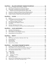
CHAPTER 17 DTP/EXTERNAL INTERRUPTS .............................................................. 313
17.1 Overview of DTP/External Interrupt ................................................................................................ 314
17.2 Block Diagram of DTP/External Interrupt ........................................................................................ 315
17.3 Configuration of DTP/External Interrupt .......................................................................................... 317
17.3.1 DTP/External Interrupt Factor Register (EIRR1) ....................................................................... 319
17.3.2 DTP/External Interrupt Enable Register (ENIR1) ...................................................................... 321
17.3.3 Detection Level Setting Register (ELVR1) ................................................................................ 323
17.3.4 External Interrupt Factor Select Register (EISSR) .................................................................... 325
17.4 Explanation of Operation of DTP/External Interrupt ....................................................................... 327
17.4.1 External Interrupt Function ........................................................................................................ 331
17.4.2 DTP Function ............................................................................................................................. 332
17.5 Precautions when Using DTP/External Interrupt ............................................................................ 333
17.6 Program Example of DTP/External Interrupt Function ................................................................... 335
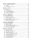
CHAPTER 18 8-/10-BIT A/D CONVERTER .................................................................... 339
18.1 Overview of 8-/10-bit A/D Converter ............................................................................................... 340
18.2 Block Diagram of 8-/10-bit A/D Converter ...................................................................................... 341
18.3 Configuration of 8-/10-bit A/D Converter ........................................................................................ 344
18.3.1 A/D Control Status Register (High) (ADCS1) ............................................................................ 346
18.3.2 A/D Control Status Register (Low) (ADCS0) ............................................................................. 349
18.3.3 A/D Data Register (ADCR0/ADCR1) ......................................................................................... 351
18.3.4 A/D Setting Register (ADSR0/ADSR1) ...................................................................................... 352
18.3.5 Analog Input Enable Register (ADER5, ADER6) ...................................................................... 356
18.4 Interrupt of 8-/10-bit A/D Converter ................................................................................................ 358
18.5 Explanation of Operation of 8-/10-bit A/D Converter ...................................................................... 359
18.5.1 Single-shot Conversion Mode ................................................................................................... 360
18.5.2 Continuous Conversion Mode ................................................................................................... 362
18.5.3 Pause-conversion Mode ............................................................................................................ 364
18.5.4 Conversion Using EI
2
OS Function ............................................................................................ 366
18.5.5 A/D-converted Data Protection Function ................................................................................... 367
18.6 Precautions when Using 8-/10-bit A/D Converter ........................................................................... 369
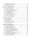
CHAPTER 19 LOW VOLTAGE DETECTION/CPU OPERATING DETECTION RESET
371
19.1 Overview of Low Voltage/CPU Operating Detection Reset Circuit ................................................. 372
19.2 Configuration of Low Voltage/CPU Operating Detection Reset Circuit .......................................... 374
19.3 Low Voltage/CPU Operating Detection Reset Circuit Register ...................................................... 376
19.4 Operating of Low Voltage/CPU Operating Detection Reset Circuit ................................................ 378
19.5 Notes on Using Low Voltage/CPU Operating Detection Reset Circuit ........................................... 379
19.6 Sample Program for Low Voltage/CPU Operating Detection Reset Circuit .................................... 380
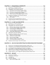
CHAPTER 20 LIN-UART ................................................................................................. 381
20.1 Overview of LIN-UART ................................................................................................................... 382
20.2 Configuration of LIN-UART ............................................................................................................. 386
20.3 LIN-UART Pins ............................................................................................................................... 391
20.4 LIN-UART Registers ....................................................................................................................... 392
20.4.1 Serial Control Register (SCR) ................................................................................................... 393


