


409
CHAPTER 20 LIN-UART
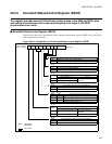
20.5.1 Reception Interrupt Generation and Flag Set Timing
The following are the reception interrupt causes: completion of reception (SSR: RDRF)
and occurrence of a reception error (SSR: PE, ORE, or FRE).
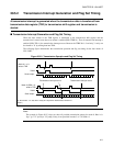
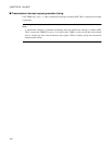
■ Reception Interrupt Generation and Flag Set Timing
The received data is stored in the RDR register if the first stop bit is detected in mode 0, 1, 2 (if SSM = 1),
3, or the last data bit was read in mode 2 (if SSM = 0).
Each flag is set if the received data is completed (RDRF = 1) and the reception error (PE, ORE, FRE) of the
Serial Status Register (SSR) was set to "1". In this case, if the reception interrupt is enabled (SSR: RIE=1),
reception interrupt occurs.
Note:
If a reception error has occurred, the Reception Data Register (RDR) contains invalid data in each
mode.
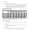
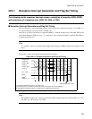
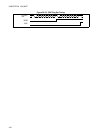
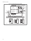
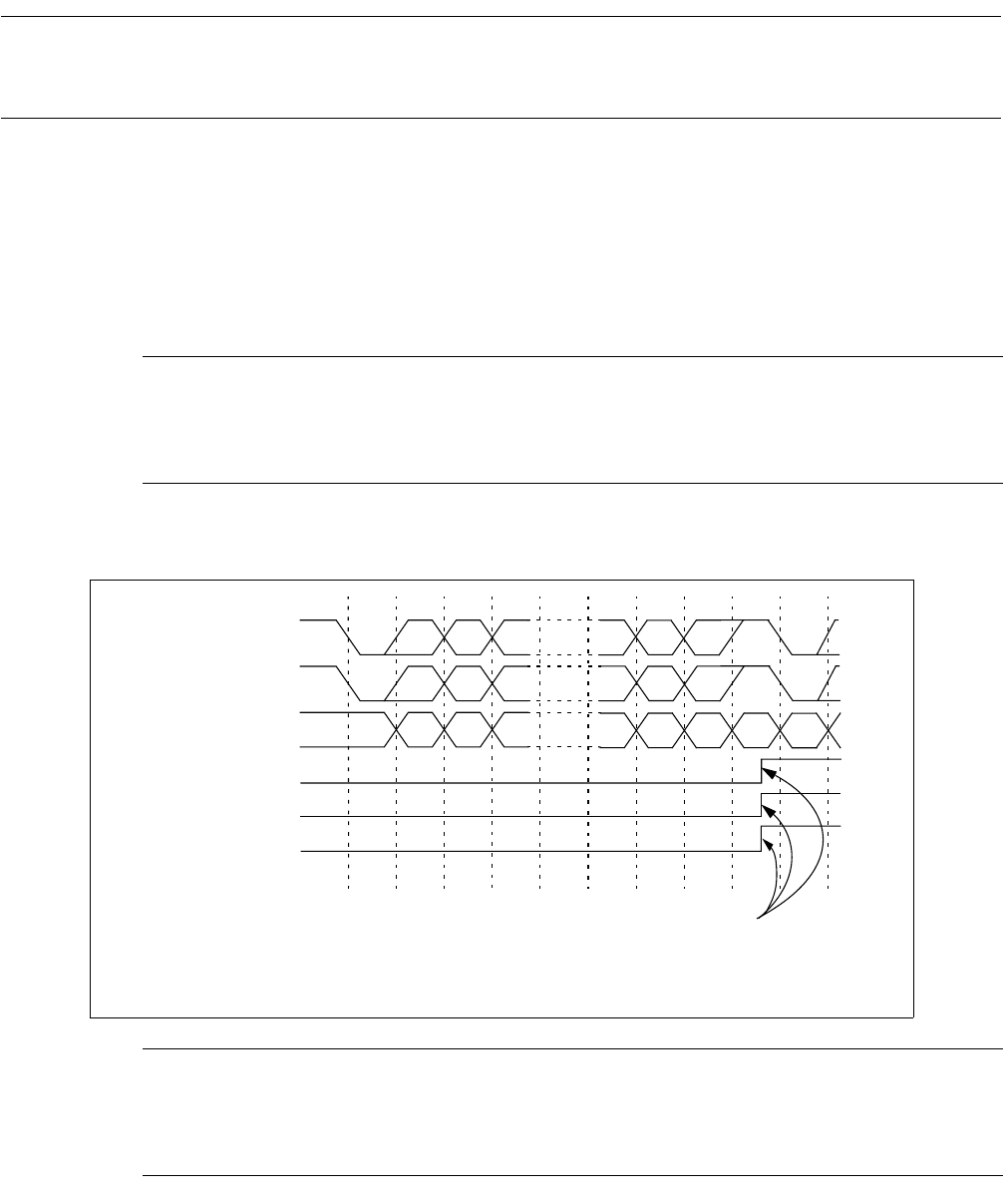
Figure 20.5-1 shows the reception operation and flag set timing.
Figure 20.5-1 Reception Operation and Flag Set Timing
Note:
The example in Figure 20.5-1 does not show all possible reception options for mode 0. Here it is: "7p1"
and "8N1" (p = "E" [even] or "O" [odd]).
RDRF
PE
*1
, FRE
ORE
*2
(RDRF = "1")
ST D0 D1 D2 D5 D6 D7/P SP ST
ST D0 D1 D2 D6 D7 A/D SP ST
D0 D1 D2 D4 D5 D6 D7 D0
Receive data
(mode 0/3)
Receive data
(mode 1)
Receive data
(mode 2)
Reception interrupt occurs
*1: The PE flag will always remain "0" in mode 1 or 3.
*2: ORE only occurs, if next data is transferred before the reception data is read (RDRF=1).
ST: Start Bit SP: Stop Bit A/D: Mode 1 (multiprocessor) address/data selection bit
...
...
...