242
CHAPTER 14 16-BIT RELOAD TIMER
14.3 Configuration of 16-bit Reload Timer
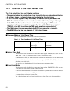
This section explains the pins, registers, and interrupt factors of the 16-bit reload timer.
■ Pins of 16-bit Reload Timer
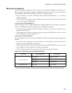
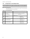
The pins of the 16-bit reload timer serve as general-purpose I/O ports. Table 14.3-1 shows the pin functions
and the pin settings required to use the 16-bit reload timer.
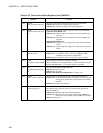
Table 14.3-1 Pins of 16-bit Reload Timer
Pin
name
Pin function Pin Setting Required for Use in 16-bit Reload Timer
P82 /
SIN0 /
INT14R /
TIN2
General-purpose I/O port/
UART input 0/
External interrupt 14/
16-bit reload timer input 2
• Port direction register: Setting for the input port (DDR8:D82=0)
• Serial control register: Setting for the reception disable
(SCR0:RXE=0)
• Disable the external interrupt (external interrupt enable register
ENIR1: EN14 = 0)
P83 /
SOT0 /
TOT2
General-purpose I/O port/
UART output 0/
16-bit reload timer output 2
• Serial control register : Setting for the transmission disable
(SCR0:TXE=0)
• Timer control status register: Enable the timer output
(TMCSR2: OUTE=1)
P53 /
AN11 /
TIN3
General-purpose I/O port/
A/D converter analog input 11/
16-bit reload timer input 3
• Port direction register : Setting for the input port
(DDR5:D53=0)
• Analog input enable register: Setting for the prohibition
(ADER5:ADE11=0)
P54 /
AN12 /
TOT3
General-purpose I/O port/
A/D converter analog input 12/
16-bit reload timer output 3
• Analog input enable register: Setting for the prohibition
(ADER5:ADE12=0)
• Timer control status register: Enable the timer output
(TMCSR3: OUTE=1)


