431
CHAPTER 20 LIN-UART
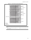
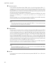
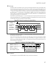
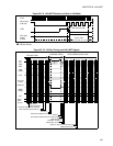
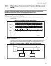
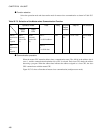
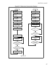
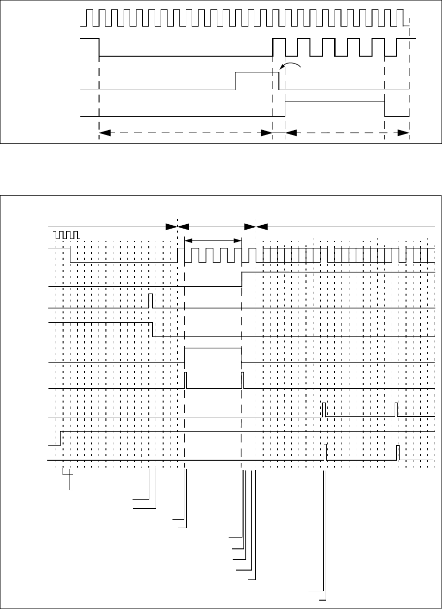
Figure 20.7-8 LIN-UART Behavior as Slave in LIN Mode
●
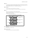
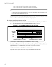
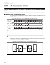
LIN bus timing
Figure 20.7-9 LIN Bus Timing and LIN-UART Signals
LBD
Synch field
Serial
clock
Serial input
(LIN bus)
ICU input
signal
(LSYN)
LBR cleared by CPU
Synch break (at 14-bit setting)
bus
RXE
LBD
(IRQ0)
RDRF
IRQ (ICU)
IRQ(ICU)
(SIN)
(IRQ0)
IRQ(ICU)
LIN
LBIE
RIE
No clock used
(calibration frame)
Old serial clock
New (calibrated) serial clock
ICU count
Reception inter-
rupt enable
LIN break begins
LIN break detected and Interrupt
IRQ cleared by CPU (LBD->0)
IRQ cleared: Begin of ICU
IRQ cleared: Calculate & set new baud rate
LBIE disable
Reception enable
Falling edge of start bit
Store one byte of received data to RDR
RDR read by CPU
Read
RDR
by CPU
ICU input
(LSYN)


