


300
CHAPTER 16 8-/16-BIT PPG TIMER
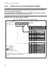
16.5 Explanation of Operation of 8-/16-bit PPG Timer
The 8-/16-bit PPG timer outputs a pulse width at any frequency and at any duty ratio
continuously.
■ Operation of 8-/16-bit PPG Timer
●
Output operation of 8-/16-bit PPG timer
• The 8-/16-bit PPG timer has two (Low-level and High-level) 8-bit reload registers (PRLLn/PRLHn and
PRLLm/PRLHm) for per channel.
• The values set in the 8-bit reload registers (PRLLn/PRLHn and PRLLm/PRLHm) are reloaded
alternately to the PPG down counters (PCNTn and PCNTm).
• After reloading the values in the PPG down counters, decrementing is performed in synchronization
with the count clocks set by the PPG count clock select bits (PPGnm: PCM2 to PCM0 and PCS2 to
PCS0).
• If the values set in the reload registers are reloaded to the PPG down counters when an underflow
occurs, the pin output is inverted.
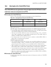
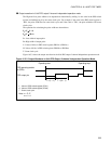
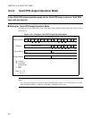
Figure 16.5-1 shows the output waveform of the 8-/16-bit PPG timer.
Figure 16.5-1 Output Waveform of 8-/16-bit PPG Timer
●
Operation modes of 8-/16-bit PPG timer
As long as the operation of the 8-/16-bit PPG timer is enabled (PPGCn: PEN0=1, PPGCm: PEN1=1), a
pulse waveform is outputted continuously from the PPG output pin. A pulse width of any frequency and
duty ratio can be set.
The pulse output of the 8-/16-bit PPG timer is not stopped until operation of the 8-/16-bit PPG timer is
stopped (PPGCn: PEN0=0, PPGCm: PEN1=0).
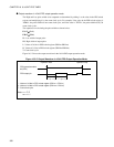
• 8-bit PPG output 2-channel independent operation mode
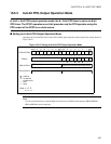
• 16-bit PPG output operation mode
• 8 + 8-bit PPG output operation mode
Note: n = C, E
m = n+1
T × (L + 1)
T × (H + 1)
Operating start Operating stop
PPG operating
enable bit (PEN)
PPG output pin
L : Value of PPG reload register (PRLL)
H : Value of PPG reload register (PRLH)
T : Count clock cycle