


356
CHAPTER 18 8-/10-BIT A/D CONVERTER
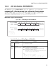
18.3.5 Analog Input Enable Register (ADER5, ADER6)
The analog input enable register enables or disables the analog input pins to be used in
the 8-/10-bit A/D converter.
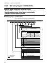
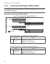
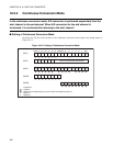
■ Analog Input Enable Register (ADER5, ADER 6)
Figure 18.3-6 Analog Input Enable Register (ADER5 to 6)
ADE15 to ADE8
0
1
Analog input disable
Analog input enable
Analog input enable bit
15 to 8 (AN15 to AN8)
Reset value
11111111B
Address
ADER5 00000BH
bit15 to bit8
R/W
ADE8ADE9
ADE10ADE11ADE12ADE13ADE14ADE15
R/WR/WR/WR/WR/WR/WR/W
R/W
ADE7 to ADE0
0
1
Analog input disable
Analog input enable
Analog input enable bit
7 to 0 (AN7 to AN0)
Reset value
11111111B
Address
ADER6 00000CH
453210
bit7 to bit0
R/W
ADE0ADE1ADE2ADE3ADE4ADE5ADE6ADE7
R/WR/WR/WR/WR/WR/WR/W
6
7
1213 11 10 9 8
14
15
: Read/Write
: Reset value
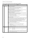
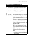
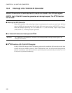
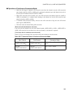
Table 18.3-8 Functions of Port 5 Analog Input Enable Register (ADER5)
Bit Name Function
bit15
to
bit8
ADE15 to ADE8:
Analog input enable
bits 15 to 8
These bits enable or disable the analog input pin (AN15 to AN8) of
A/D conversion arranged on port 5.
When set to "0": Disables analog input
When set to "1": Enables analog input
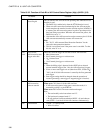
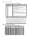
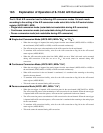
Table 18.3-9 Functions of Port 6 Analog Input Enable Register (ADER6)
Bit Name Function
bit0
to
bit7
ADE7 to ADE0:
Analog input enable
bits 7 to 0
These bits enable or disable the analog input pin (AN7 to AN0) of A/
D conversion arranged on port 6.
When set to "0": Disables analog input
When set to "1": Enables analog input