


597
APPENDIX B Instructions
B.7 How to Read the Instruction List
Table B.7-1 describes the items used in the F
2
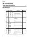
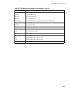
MC-16LX Instruction List, and Table B.7-2
describes the symbols used in the same list.
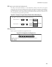
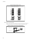
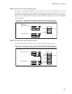
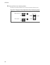
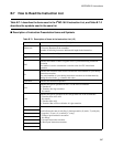
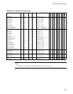
■ Description of Instruction Presentation Items and Symbols
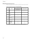
Table B.7-1 Description of Items in the Instruction List (1/2)
Item Description
Mnemonic
Uppercase, symbol: Represented as is in the assembler.
Lowercase: Rewritten in the assembler.
Number of following lowercase: Indicates bit length in the instruction.
# Indicates the number of bytes.
Indicates the number of cycles.
RG
Indicates the number of times a register access is performed during instruction
execution.
The number is used to calculate the correction value for CPU intermittent
operation.
B
Indicates the correction value used to calculate the actual number of cycles during
instruction execution.
The actual number of cycles during instruction execution can be determined by
adding the value in the column to this value.
Operation Indicates the instruction operation.
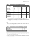
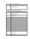
LH
Indicates the special operation for bits 15 to 08 of the accumulator.
Z: Transfers 0.
X: Transfers after sign extension.
-: No transfer
AH
Indicates the special operation for the 16 high-order bits of the accumulator.
*: Transfers from AL to AH.
-: No transfer
Z: Transfers 00 to AH.
X: Transfers 00
H
or FF
H
to AH after AL sign extension.
I
Each indicates the state of each flag: I (interrupt enable), S (stack), T (sticky bit),
N (negative), Z (zero), V (overflow), C (carry).
*: Changes upon instruction execution.
-: No change
Z: Set upon instruction execution.
X: Reset upon instruction execution.
S
T
N
Z
V
C