


585
APPENDIX B Instructions
●
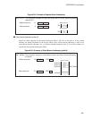
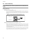
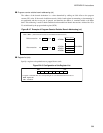
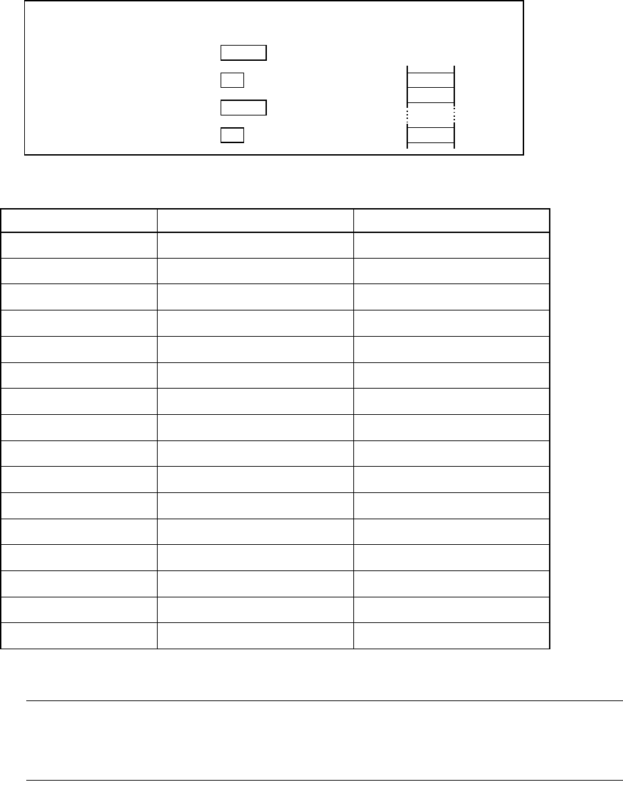
Vector Addressing (#vct)
Specify vector data in an operand to indicate the branch destination address. There are two sizes for vector
numbers: 4 bits and 8 bits. Vector addressing is used for a subroutine call or software interrupt instruction.
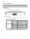
Figure B.3-11 Example of Vector Addressing (#vct)
Note:
When the program bank register (PCB) is FF
H
, the vector area overlaps the vector area of INT #vct8
(#0 to #7). Use vector addressing carefully (see Table B.3-2 ).
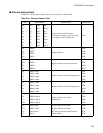
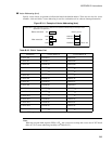
Table B.3-2 CALLV Vector List
Instruction Vector address L Vector address H
CALLV #0
XXFFFE
H
XXFFFF
H
CALLV #1
XXFFFC
H
XXFFFD
H
CALLV #2
XXFFFA
H
XXFFFB
H
CALLV #3
XXFFF8
H
XXFFF9
H
CALLV #4
XXFFF6
H
XXFFF7
H
CALLV #5
XXFFF4
H
XXFFF5
H
CALLV #6
XXFFF2
H
XXFFF3
H
CALLV #7
XXFFF0
H
XXFFF1
H
CALLV #8
XXFFEE
H
XXFFEF
H
CALLV #9
XXFFEC
H
XXFFED
H
CALLV #10
XXFFEA
H
XXFFEB
H
CALLV #11
XXFFE8
H
XXFFE9
H
CALLV #12
XXFFE6
H
XXFFE7
H
CALLV #13
XXFFE4
H
XXFFE5
H
CALLV #14
XXFFE2
H
XXFFE3
H
CALLV #15
XXFFE0
H
XXFFE1
H
Note: A PCB register value is set in XX.
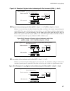
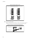
CALLV #15
0 0 0 0PC
F FPCB
F F
D 0
D 0 0 0PC
PCB
FFFFE1H
0 0
FFFFE0H
E F
FFC000H CALLV
#15
Before execution
After execution
Memory space
(This instruction causes a branch to the address indicated by the interrupt vector
specified in an operand.)