


115
CHAPTER 6 CLOCK SUPERVISOR
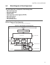
6.4 Operating Mode of Clock Supervisor
This section explains all the operating modes of the Clock Supervisor.
■ Operating Mode in Initialized State
The CR oscillation circuit, the main clock supervisor and the sub-clock supervisor are enabled before the
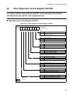
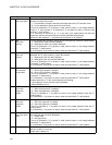
clock supervisor control register (CSVCR) is set by the user program.
• After power-on reset or reset of the low voltage detection, the CR oscillation circuit is enabled with "T"
suffix product. After power-on reset or external reset, the CR oscillation circuit is enabled without "T"
suffix product.
• If the main clock goes off after a lapse of the oscillation stability waiting time (2
11
/HCLK), the main
clock monitor function will be immediately enabled to cause reset to occur.
• If the main clock goes off before a lapse of the oscillation stability waiting time after power-on reset,
the main clock monitor function will cause reset after a lapse of the 2
12
cycle of CR oscillation clock
(approximately 41 ms for the CR oscillation of 100 kHz).
• If the main clock goes off during the period of power-on reset, the device will retain the reset state.
• After it passes of 2
18
cycles of the CR oscillation clock (For about 2.6 s:CR oscillation 100 kHz), the
sub-clock supervisor is valid.
• When the main clock is stopped on the main clock supervisor enable state, the main clock is replaced
with the CR oscillation clock, MM bit is set to one, and the reset is generated.
• When the sub clock is stopped on the sub clock mode, the sub clock is replaced with the CR oscillation
two dividing frequency clock, SM bit is set to one, and the reset is generated. When the sub clock is
stopped on the main clock mode, the sub clock is replaced with the CR oscillation two dividing
frequency clock, SM bit is set to one. However, the reset is not generated at the sub-clock mode
transition because the initial value of SRST bit is "0".
■ Prohibition Setting of CR Oscillation Circuit and Clock Supervisor
In the following settings, it is assumptions that the CR oscillation circuit, the main clock supervisor, and the
sub-clock supervisor are operating.
• MSVE(CSVCR:bit3) is set to 0 and the main clock supervisor is set disable.
• SSVE(CSVCR:bit2) is set to 0 and the sub clock supervisor is set disable.
• The RCE bit (bit4 of CSVCR) is set to 0 and the CR oscillation circuit is set disable. Please set it after
checking that the main clock and the sub-clock supervisor are disabled, and both SM and MM (bit4 of
CSVCR) are 0. Do not set RCE to 0 when either SM or MM is one.
■ Reoperating Setting of CR Oscillation Circuit and Clock Supervisor
In the following settings, it is assumptions that the CR oscillation circuit, the main clock supervisor, and the
sub-clock supervisor are stopped.
• RCE(CSVCR:bit4) is set to 1 and the CR oscillation circuit is set enable.
• MSVE(CSVCR:bit3) is set to 1 and the main clock supervisor is set enable. Please note the
programming of software to do after 10 µs or more has passed since the CR oscillation circuit was set
enable.