


413
CHAPTER 20 LIN-UART
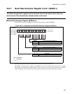
20.6 LIN-UART Baud Rates
One of the following can be selected for the LIN-UART transmission/reception clock
source:
• Dedicated baud rate generator (Reload Counter)
• Input external clock to baud rate generator (Reload Counter)
• External clock (directly use SCKn pin input clock)
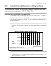
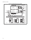
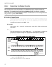
■ LIN-UART Baud Rate Selection
The baud rate selection circuit is designed as shown below. One of the following three types of baud rates
can be selected:
●
Baud rates determined using the dedicated baud rate generator (reload counter) with internal clock
LIN-UART has two independent internal reload counters for transmission and reception serial clock. The
baud rate can be selected via the 15-bit reload value determined by the Baud Rate Generator Register 0 and
1 (BGR0/1).
The reload counter divides the internal clock by set value.
It is used in asynchronous or synchronous (master) mode. Internal clock and baud rate generator clock is
selected for the setting of clock source (SMR: EXT=0, OTO=0).
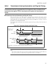
●
Baud rates determined using the dedicated baud rate generator (reload counter) with external clock
An external clock source can also be connected internally to the reload counter. The baud rate can be
selected via the 15-bit reload value determined by the baud rate generator register 0 and 1 (BGR 0/1). The
reload counter divides the external clock by set value. It is used in asynchronous mode. External clock and
baud rate generator clock is selected for the setting of the clock source (SMR: EXT=1, OTO=0). This was
designed to use quartz oscillators with special frequencies and having the possibility to divide them.
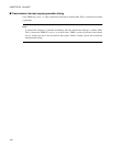
●
Baud rates determined using external clock (one-to-one mode)
The clock input from LIN-UART clock pulse input pins (SCKn) is used as it is (synchronous mode 2 slave
operation (ECCR: MS=1)). It is used in synchronous mode (slave). External clock and direct use of
external clock is selected for the setting of clock source (SMR: EXT=1, OTO=1).