


461
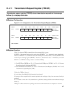
21.4.6 Receive and Transmit Error Counters (RTEC)
The receive and transmit error counters indicate the counts for transmission errors and
reception errors defined in the CAN specifications. These registers can only be read.
■ Register Configuration
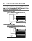
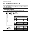
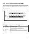
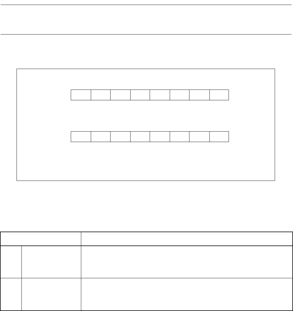
Figure 21.4-5 Configuration of the Receive and Transmit Error Counters
■ Register Function
Address bit15 bit14 bit13 bit12 bit11 bit10 bit9 bit8 RTEC1(Upper)
CAN1: 007D05
H
TEC7 TEC6 TEC5 TEC4 TEC3 TEC2 TEC1 TEC0 Reset value
0 0 0 0 0 0 0 0
B
RRRRRRRR
Address bit7 bit6 bit5 bit4 bit3 bit2 bit1 bit0 RTEC1(Lower)
CAN1: 007D04
H
REC7 REC6 REC5 REC4 REC3 REC2 REC1 REC0 Reset value
0 0 0 0 0 0 0 0
B
RRRRRRRR
R : Read only
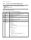
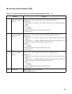
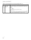
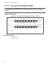
Table 21.4-5 Function of Each Bit of the Receive and Transmit Error Counters (RTEC)
Bit Name Function
bit15
to
bit8
TEC7 to TEC0:
Transmit error counter
bits
These are transmit error counters.
TEC7 to TEC0 values indicate 0 to 7 when the counter value is more than 256, and the
subsequent increment is not counted for counter value. In this case, Bus Off is indicated
for the node status (NS1 and NS0 of control status register CSR = 11).
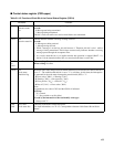
bit7
to
bit0
REC7 to REC0:
Receive error counter
bits
These are receive error counters.
REC7 to REC0 values indicate 0 to 7 when the counter value is more than 256, and the
subsequent increment is not counted for counter value. In this case, Error Passive is
indicated for the node status (NS1 and NS0 of control status register CSR = 10).