


325
CHAPTER 17 DTP/EXTERNAL INTERRUPTS
17.3.4 External Interrupt Factor Select Register (EISSR)
The external interrupt factor select register (EISSR) can change the assignment of the
external interrupt pin. This allows the external interrupt. Also, the function such as CAN
wakeup is implemented.
■ Selection of External Interrupt Factor
The external interrupt pin of the upper 8-bit is assigned to INT13, INT11, INT10, and INT8 normally and
shares the port 5 and pin. In the external bus mode, the port 0 cannot be used as the external interrupt pin.
The pin is switched by the external interrupt factor select register (EISSR). In addition, because INT15R,
INT14R, INT12R, and INT9R share the function such as CAN input pin, the function such as CAN wakeup
can be implemented.
See Table 17.3-8 for the pin function of INT15R, INT14R, INT12R, and INT9R.
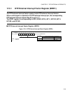
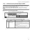
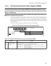
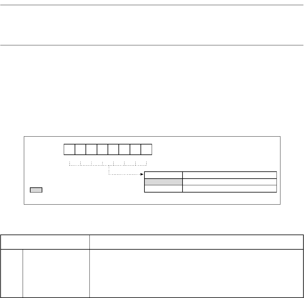
Figure 17.3-5 DTP/external Interrupt Factor Select Register (EISSR)
EISSR: 0000CE
H
Address
453210
bit7 to bit0
6
7
R/W
X
R/WR/WR/WR/WR/WR/WR/WR/W
0
1
INT15R to INT8R
00000000
B
INT15R INT14RINT13R INT12R INT11RINT10R
INT9R INT8R
Reset value
External interrupt factor select bit
: Read/Write
: Undefined
: Reset value
Set pins INT15 to INT8 as external interrupt factor
Set pins INT15R to INT8R as external interrupt factor
* See Table 17.3-8 "External interrupt factor select (upper 8-bit)" for the pin
assignment of INT15R to INT8R.
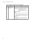
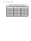
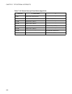
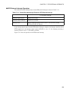
Table 17.3-7 Function of DTP/external Interrupt Factor Select Register (EISSR)
Bit Name Function
bit7
to
bit0
INT15R to INT8R:
External interrupt factor
select bits
When these bits are set to "1", the input pin of the corresponding external interrupt
factor (upper 8-bit) is assigned to the INT15R to INT8R.
When set to "0" : The external interrupt factor of the upper 8-bit is assigned to
INT15 to INT8 pins.
When set to "1": The external interrupt factor of the upper 8-bit is assigned to the
INT15R to INT8R pins.